 If you would like to take part in the club build project then the following description may help.
N.B. This is not the only way to build The Sleeker, its just how I did it.
—————————————————————————————————————————————————-
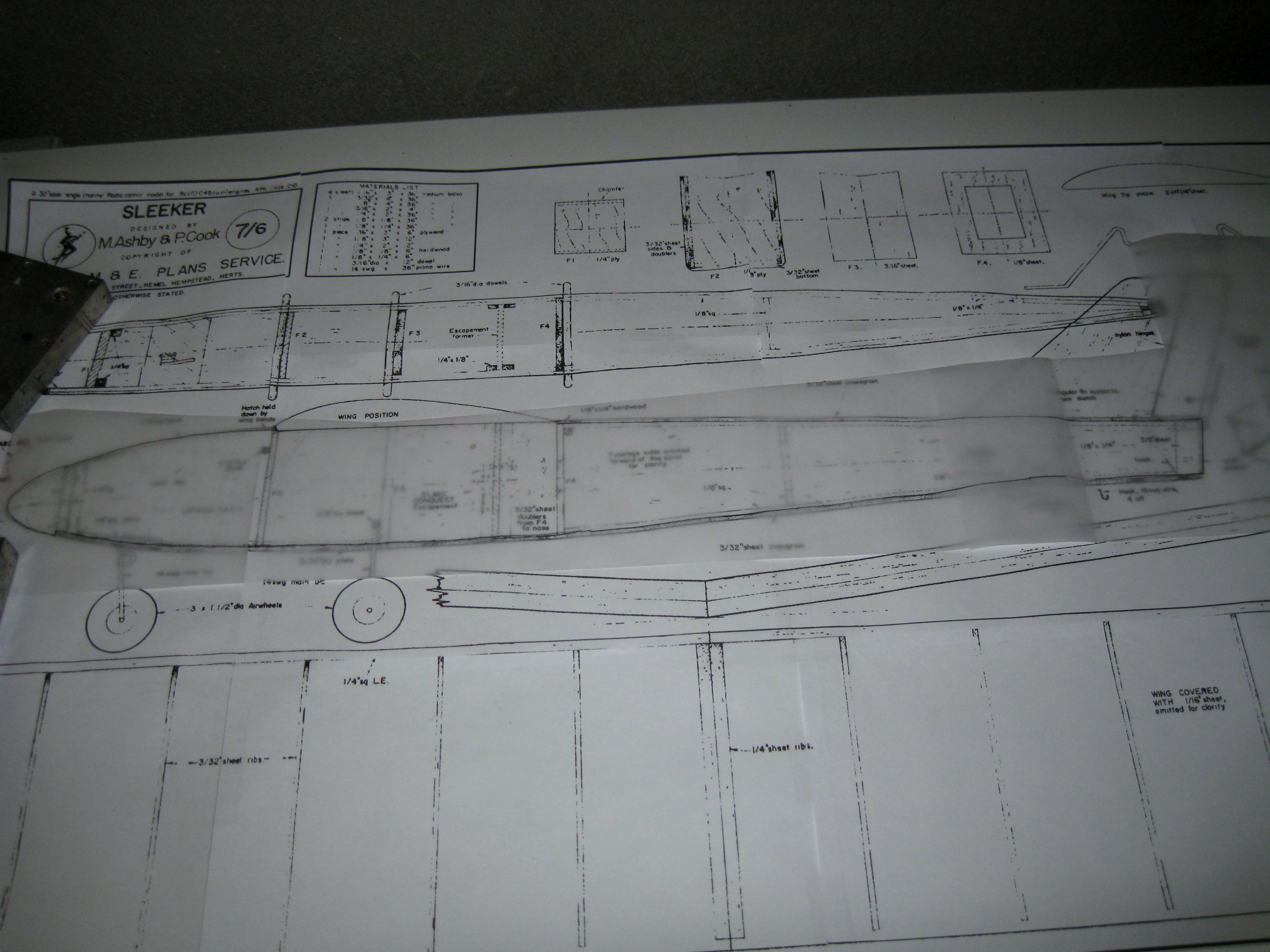
You can download the plan and original build article here:
https://outerzone.co.uk/plan_details.asp?ID=8839
https://outerzone.co.uk/planfile_supplement/8839/Sleeker_RC_oz8839_article.pdf
This is the updated build article published in September 2016 issue of RCM&E.
If you decide to download and use the plan above you can proceed as follows:
Save it to a memory stick and take it to a Print Shop where they will produce a full size copy for you, or:
- Open the plan
- Select, File, Print.
- Click on Poster
- Set Tile Scale to 100%
- Make sure the Cut Marks and Portrait Orientation are selected.
- The plan will print out on A4 sheets which can then be aligned and taped together.
—————————————————————————————————————————————————
Here are the Templates for the Tailplane, Fin, Wing Ribs and Tips and Formers..
—————————————————————————————————————————————————-
These tools should be useful for the build.
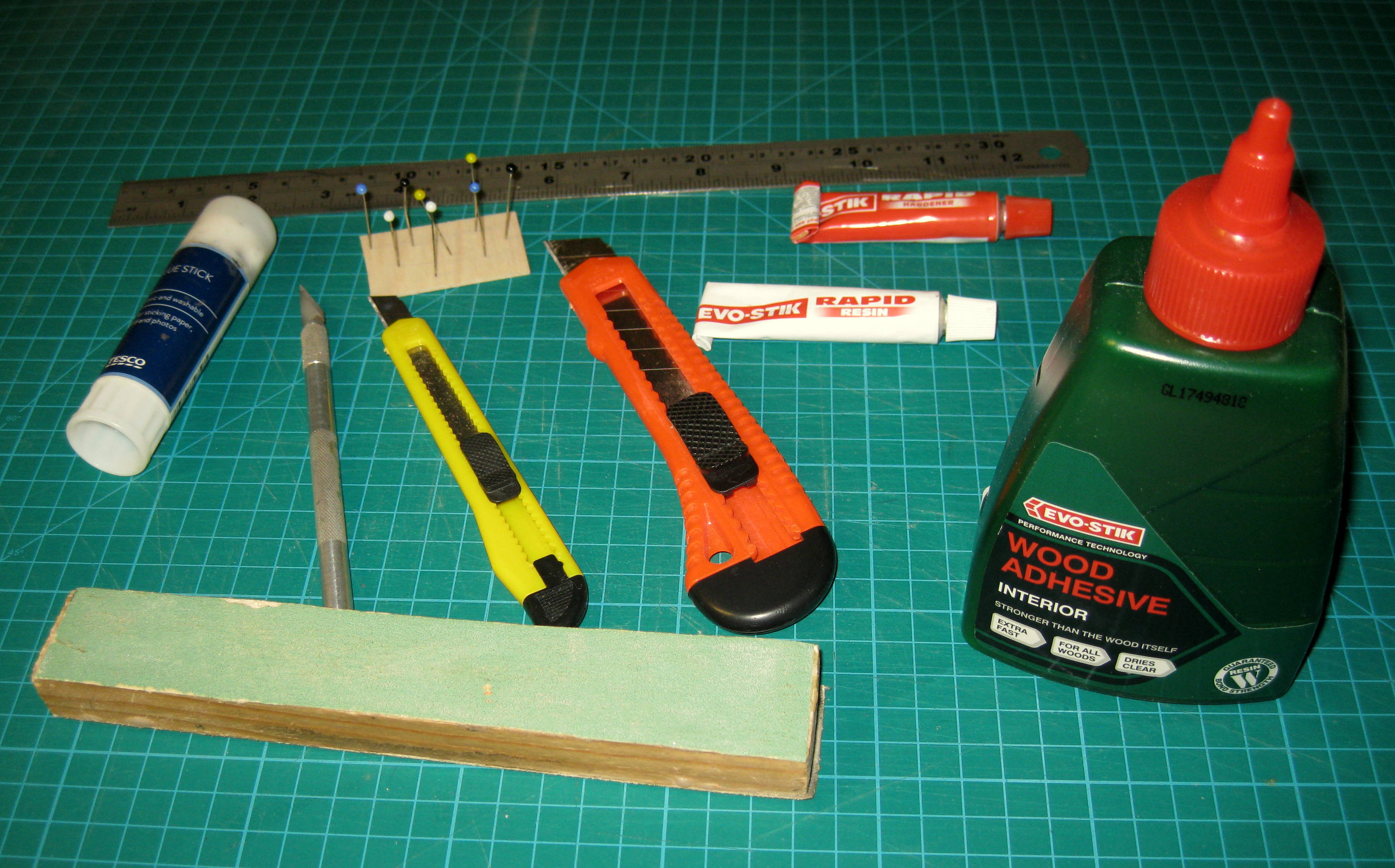
- Straight Edge
- Pritt Stick
- Glass Headed Pins
- Two Part Epoxy Adhesive.
- Modelling Knife.
- Retractable Knives. (Pound Shop)
- PVA Wood Glue
- Sanding Block. (A block of wood with fine grade paper on one side and medium on the other)
————————————————————————————————————————————————–
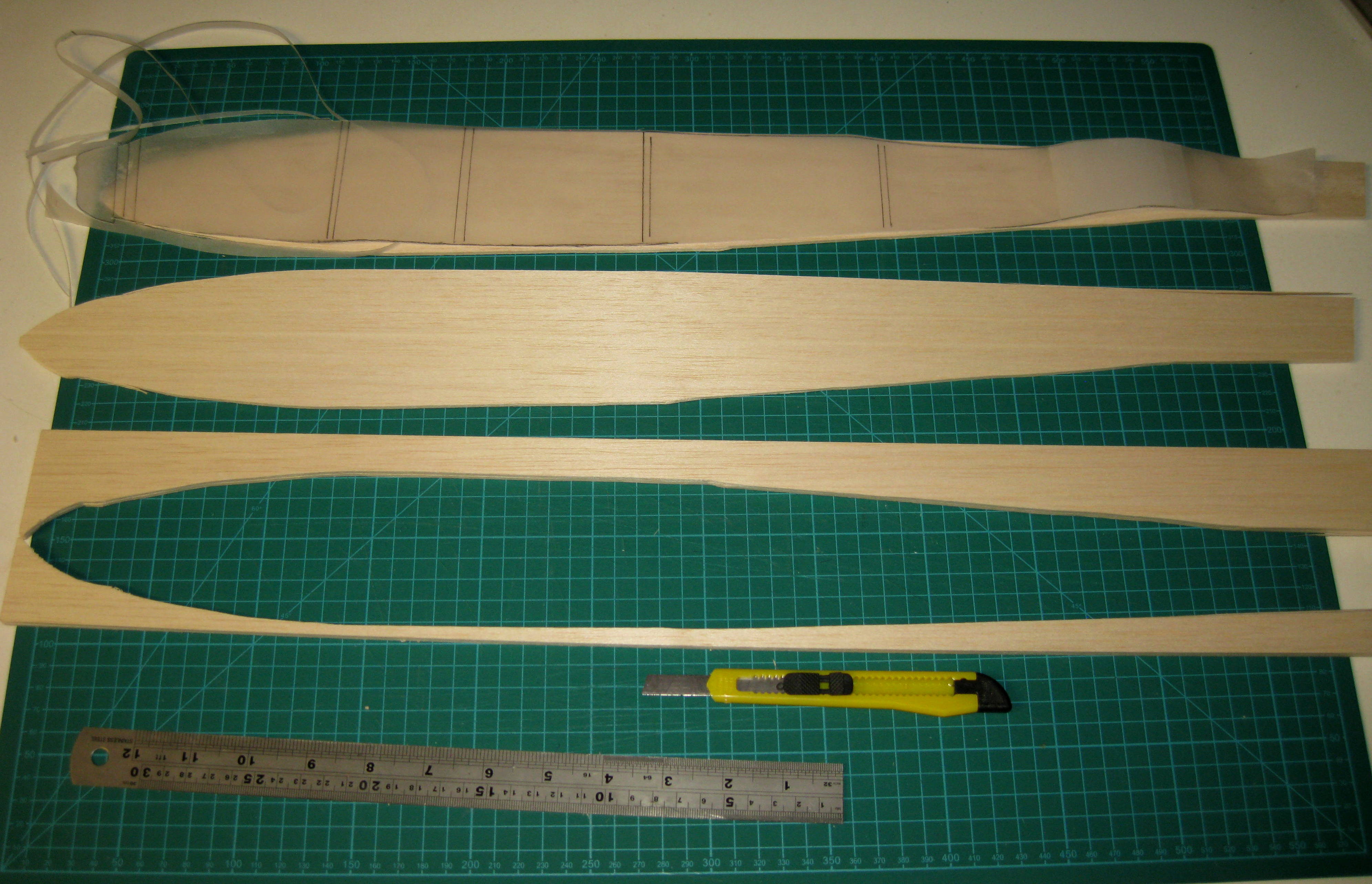
First, it is advisable to assemble a complete kit of parts. Cutting out the parts as you need them is tedious and time consuming.
Cut parts slightly oversize and then sand them tp the correct profile.
Start with the fuselage sides;
Trace the outline of the fuselage from the plan.
 Spot glue two sheets of balsa together and stick the the traced outline of the sides to them. This will ensure that the two sides will be identical when you cut them out.
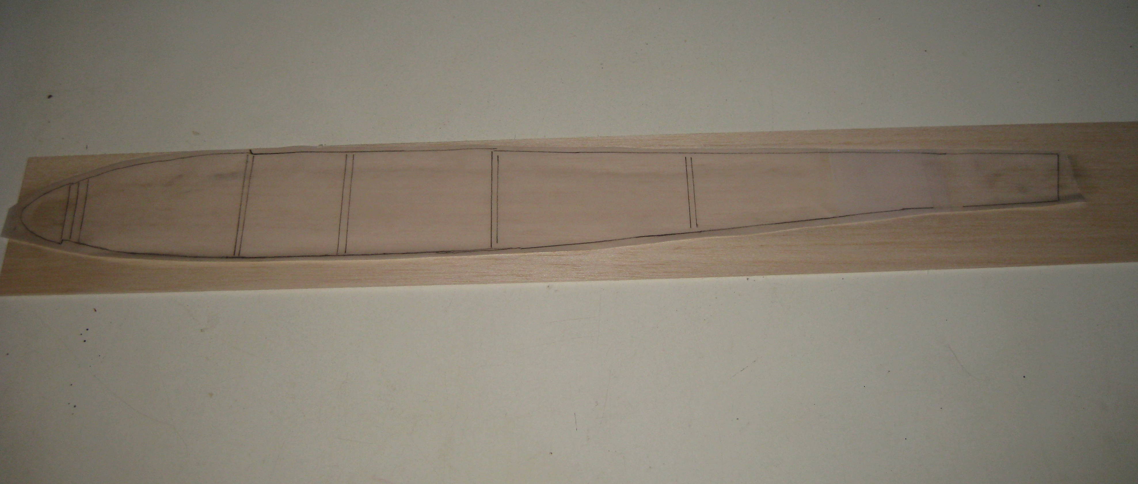 Mark the positions of the formers.
 —————————————————————————————————————————————————
Next cut out the wing ribs using the wood left over from the fuselage sides.
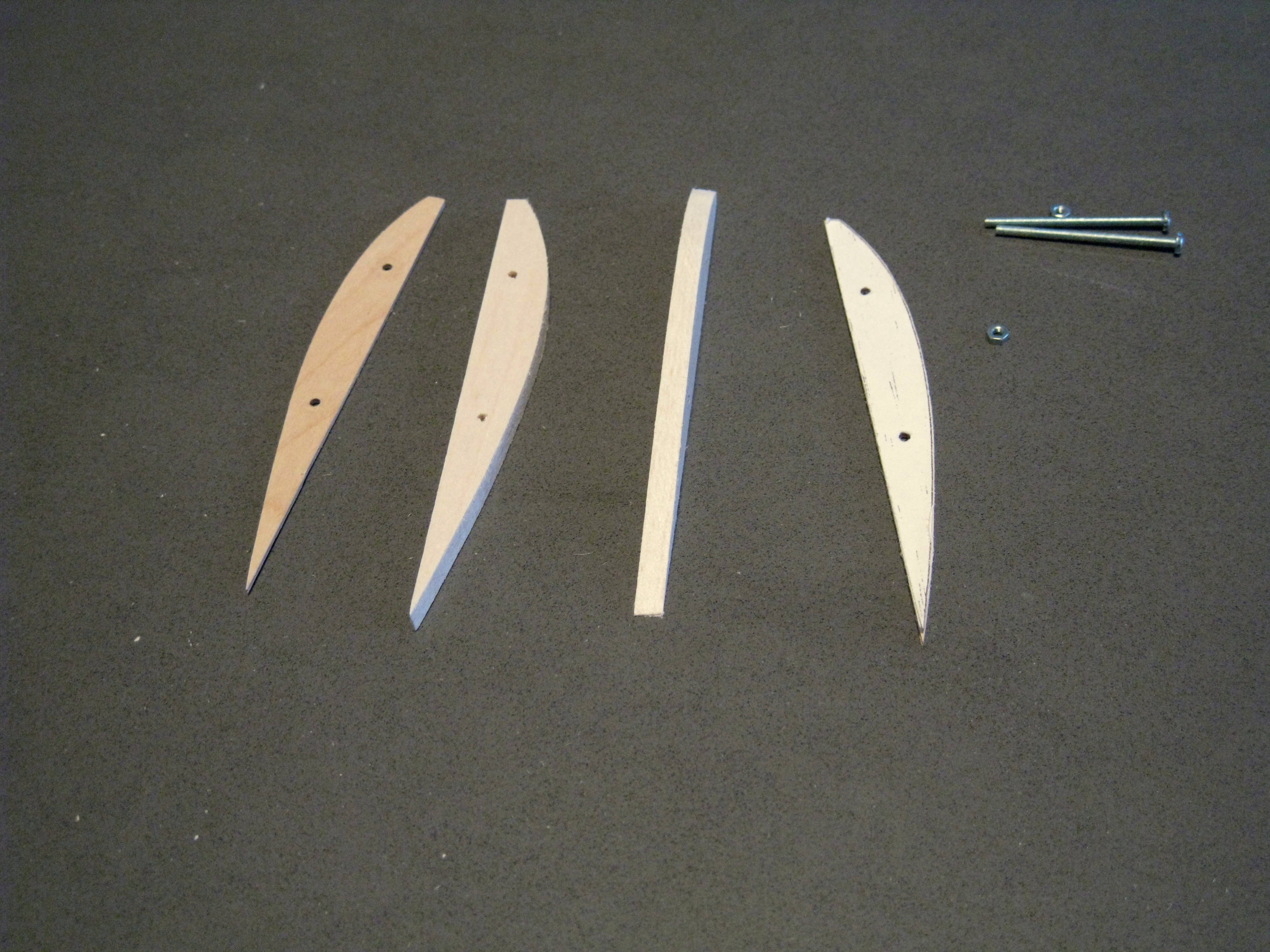
First, print two copies of the wing rib templates above. Then Pritt Stick these to some scrap thin ply. (2mm or 1mm)
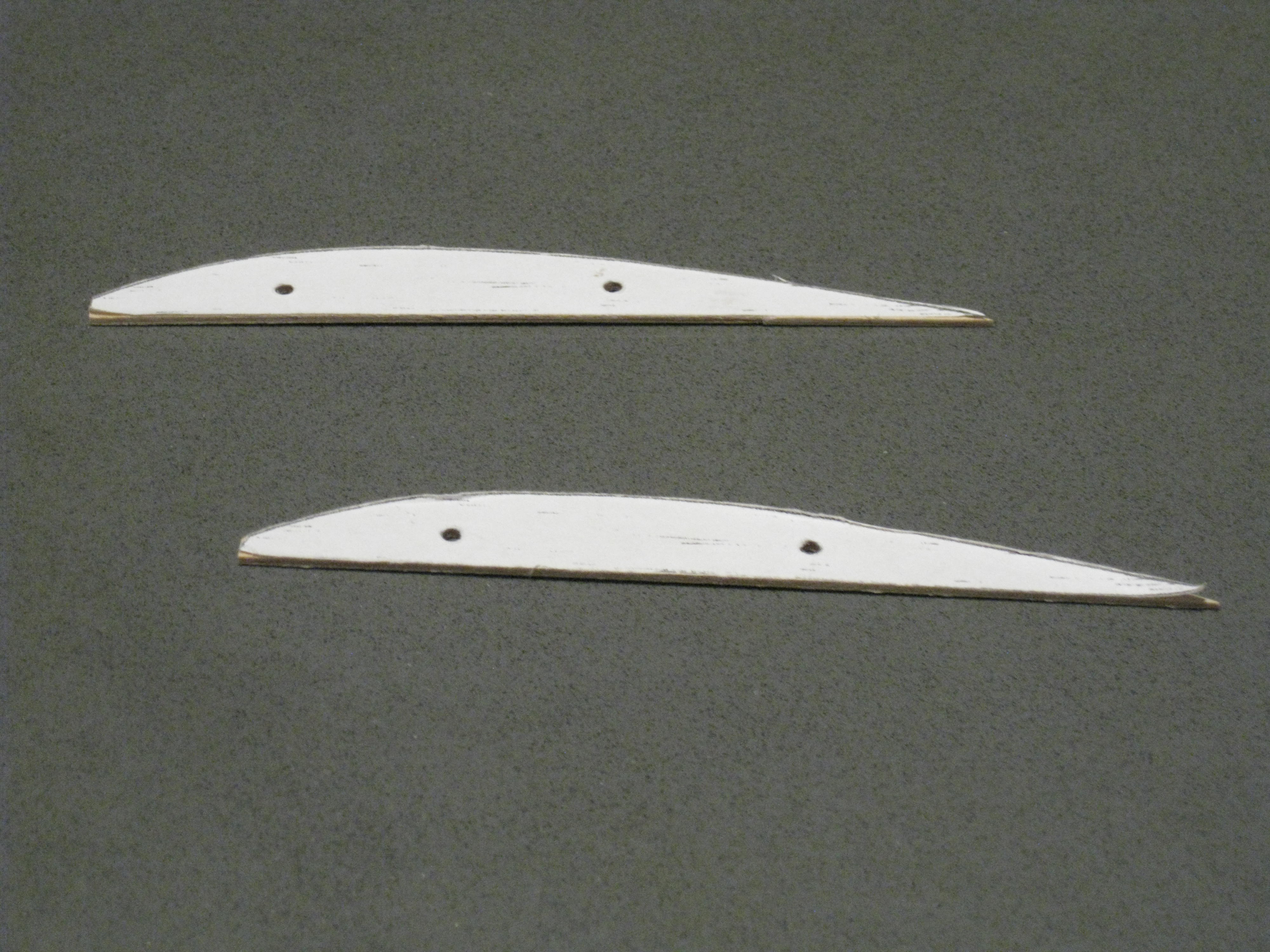
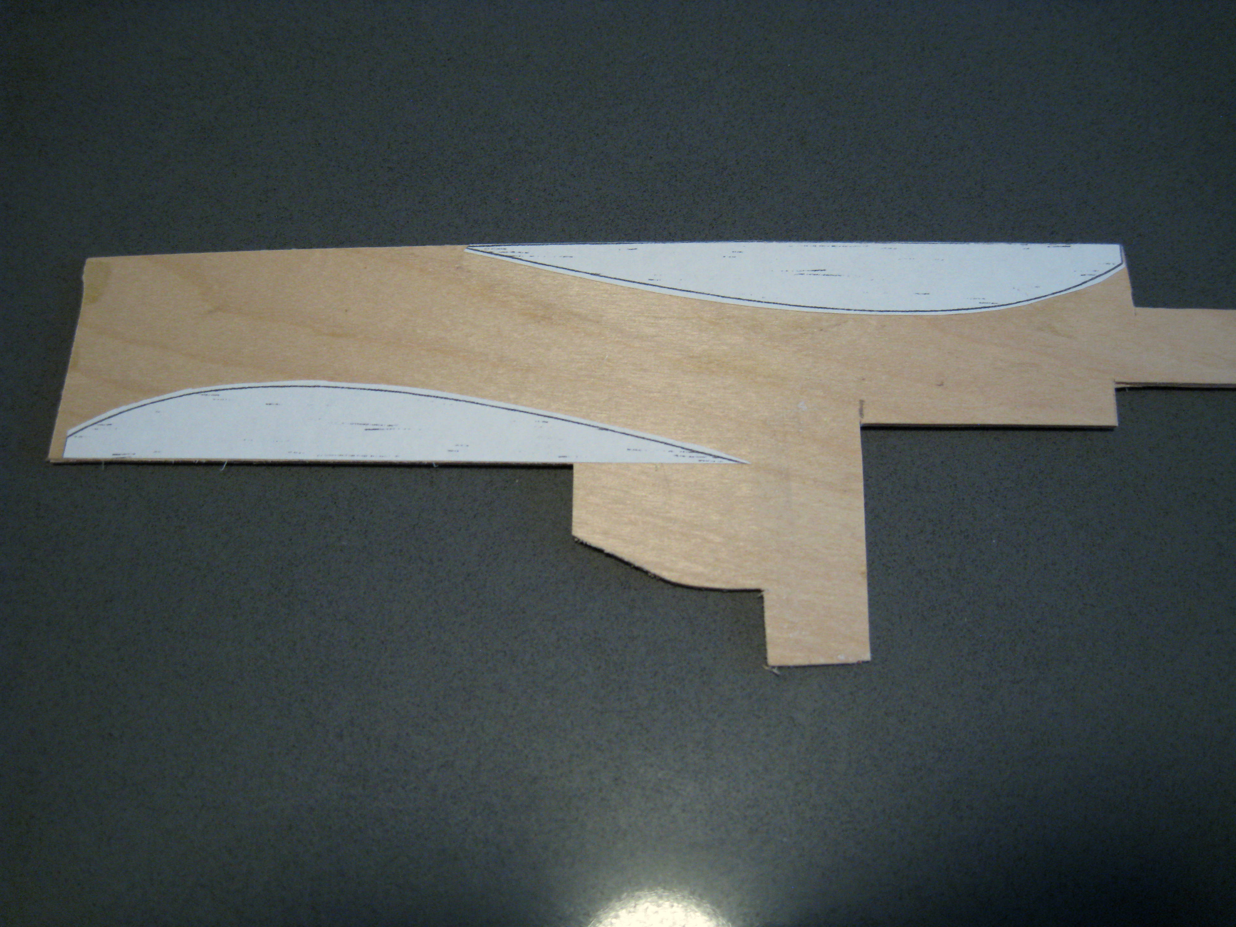 Cut them out and then sand them to the correct profile, pin them together and drill two 3mm holes.
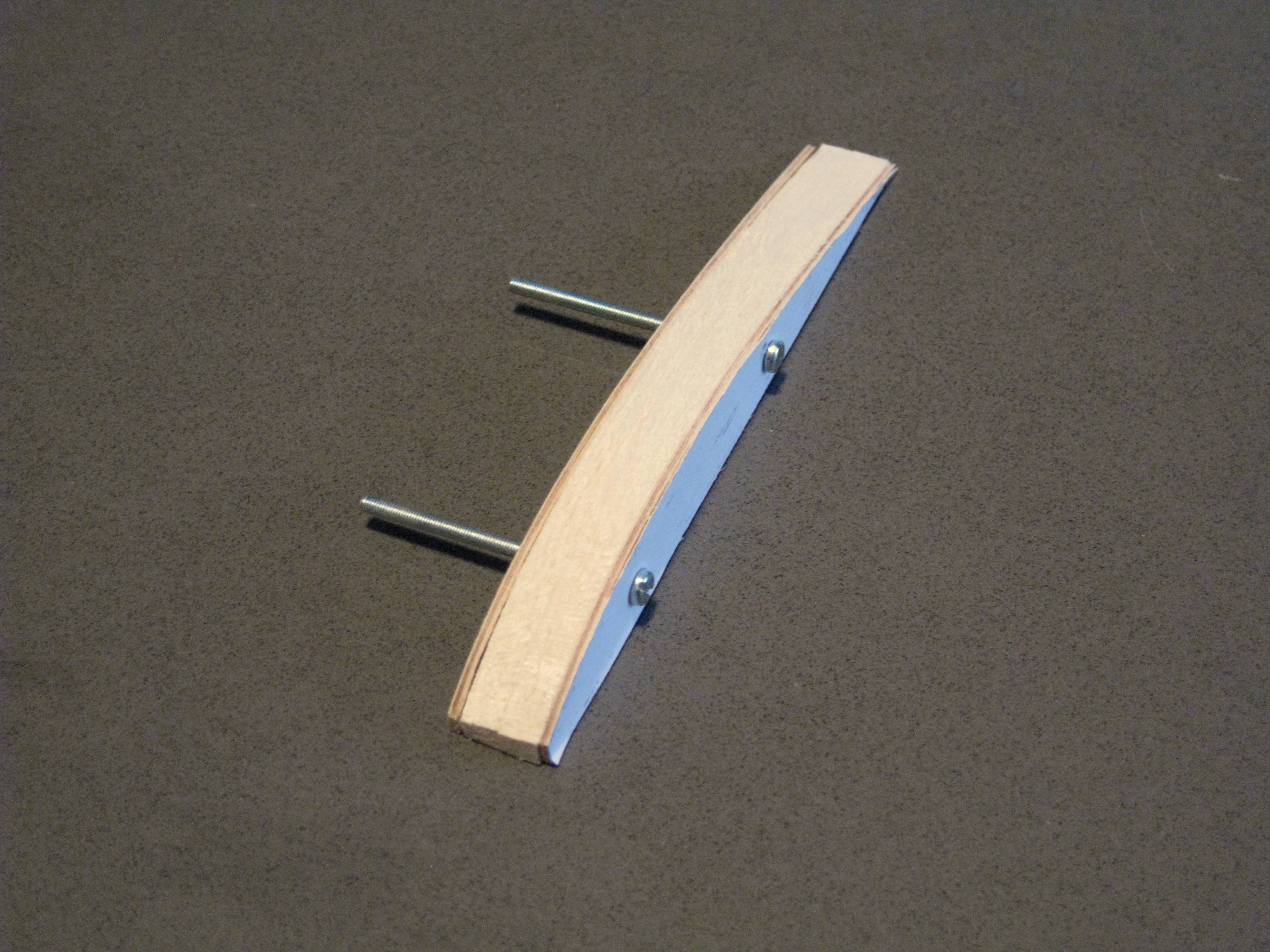
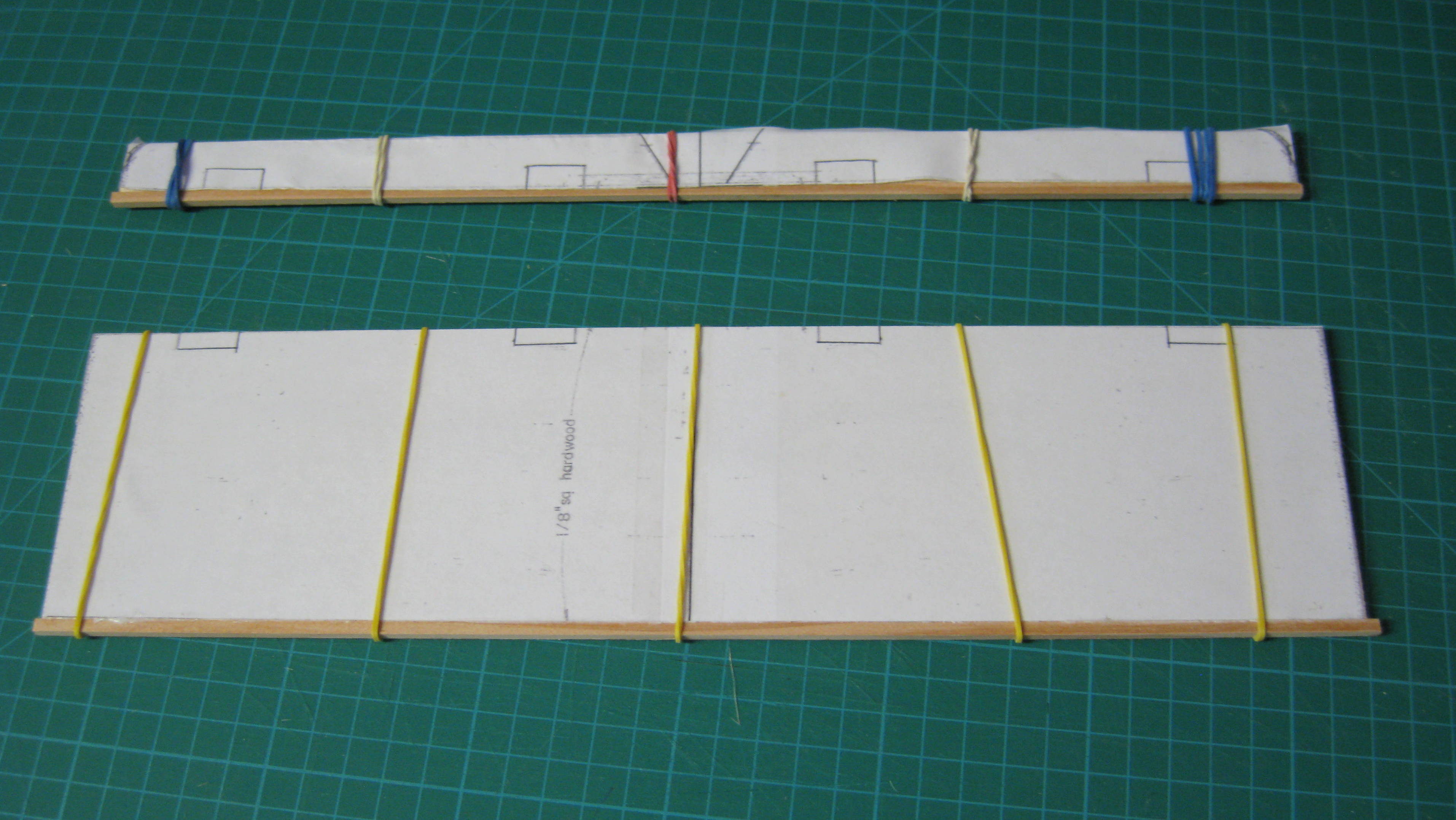
 Prepare some scrap balsa pieces which are the approximate shape of a rib.
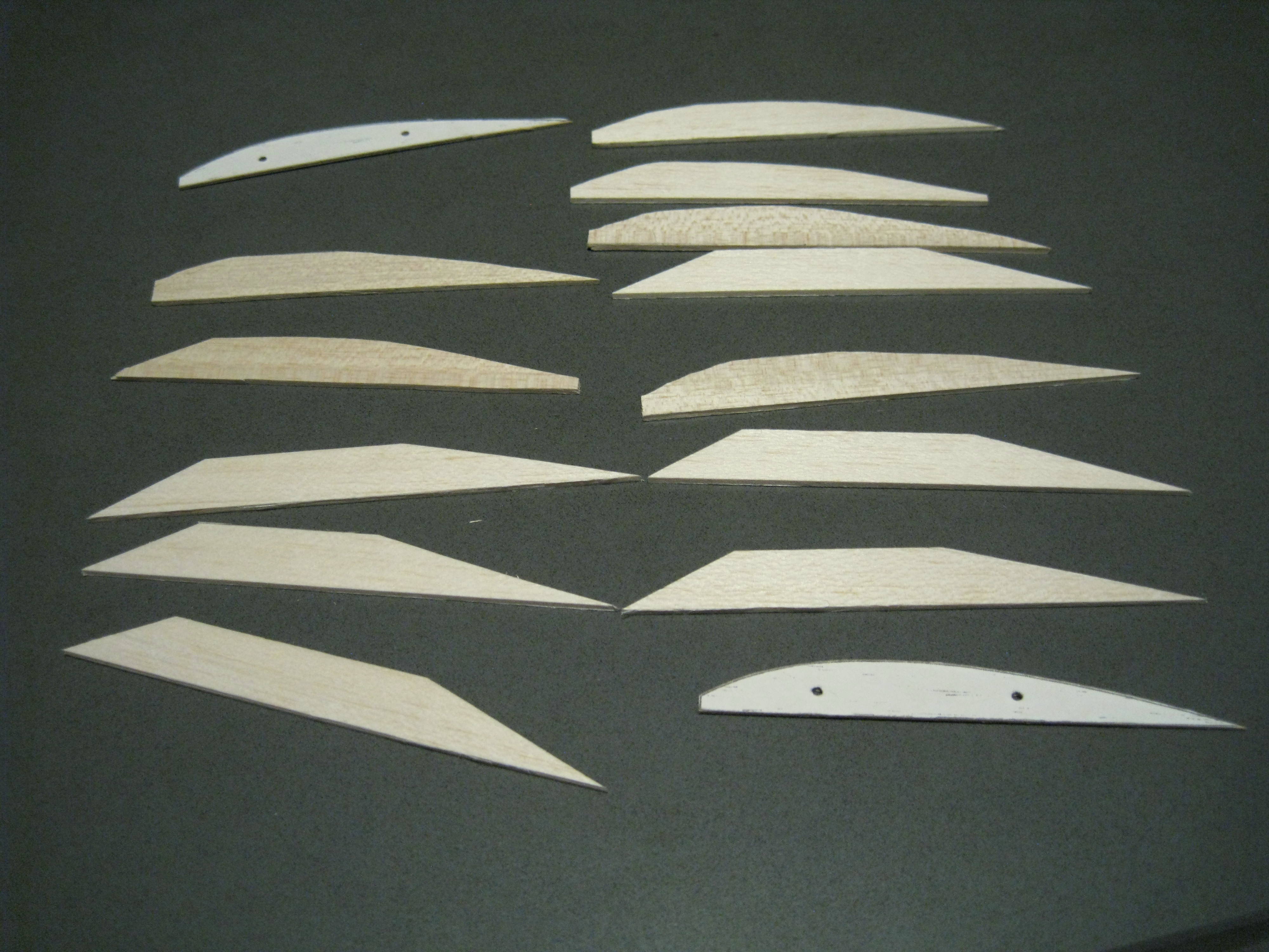 Sandwich them together between the two ply templates.
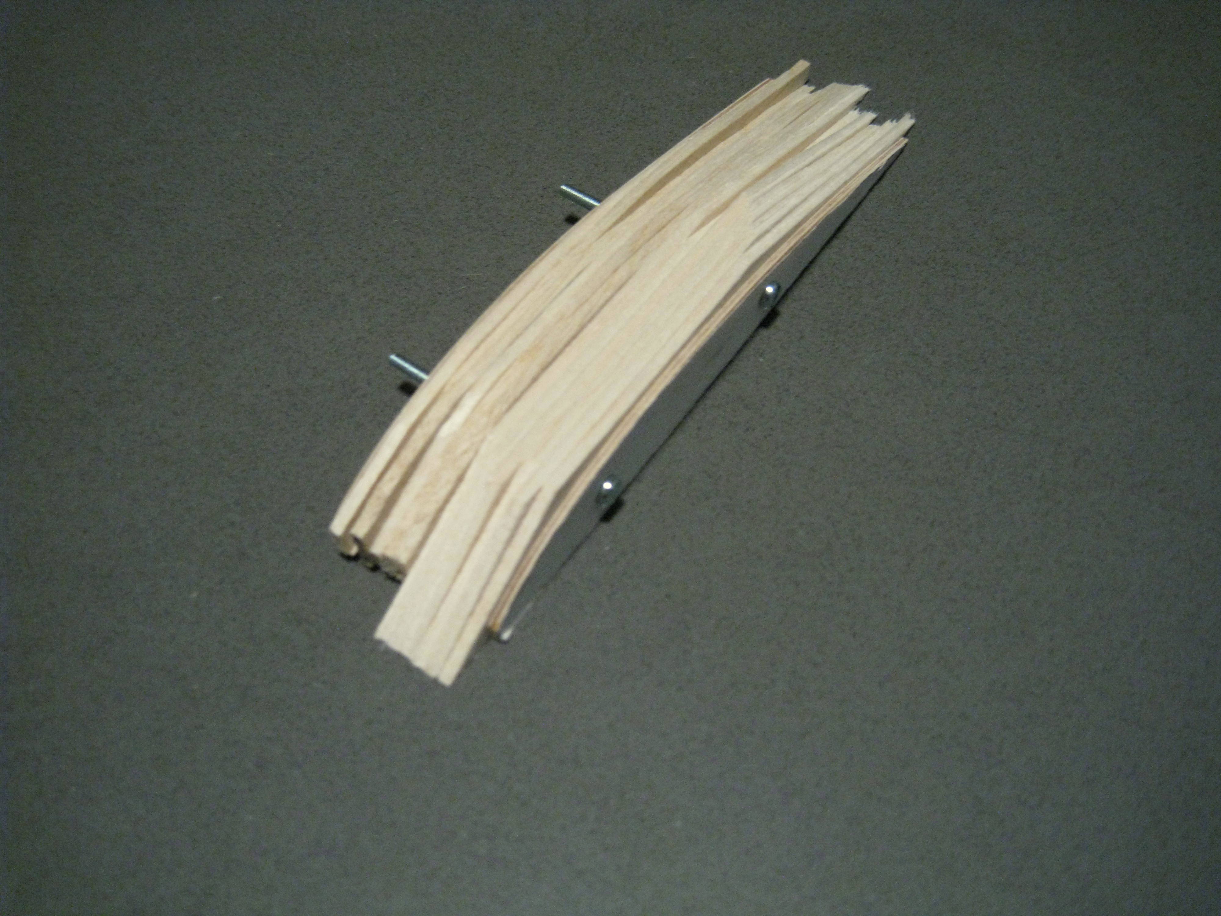 Carefully trim and sand the assembly to the profile of the templates.
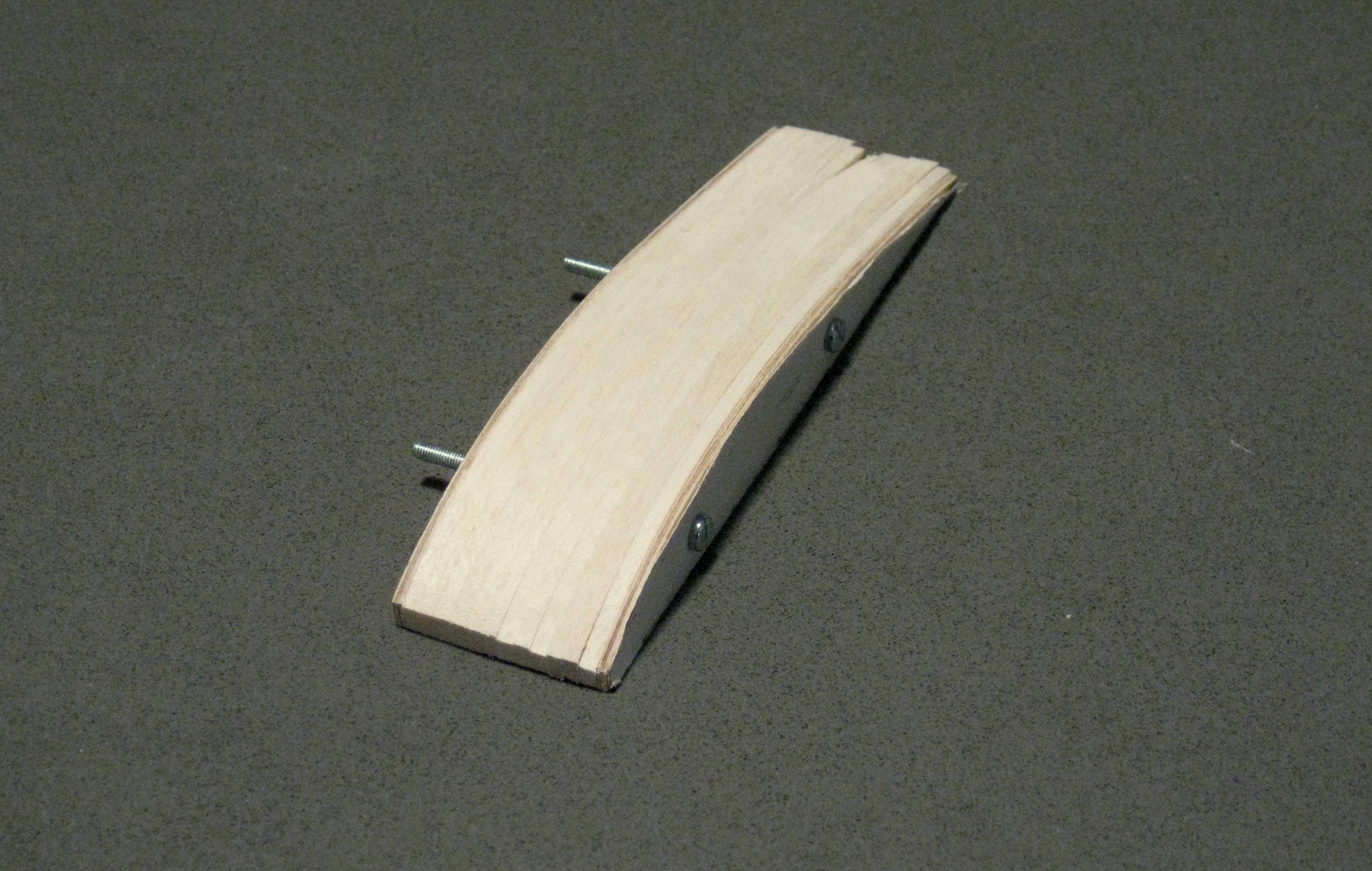 Remove the screws and you have a complete set of identical wing ribs.
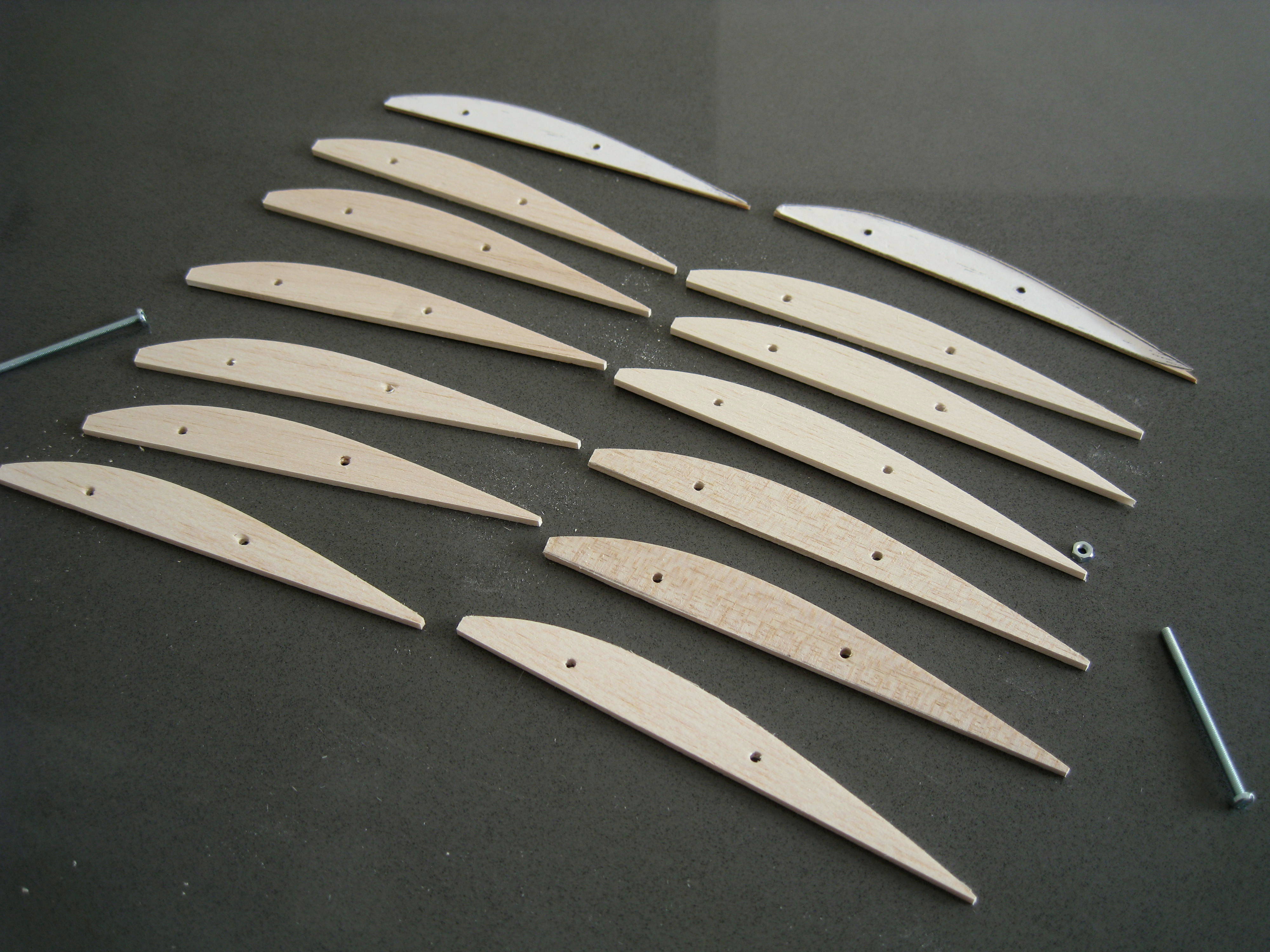 The two 6mm root ribs are produced in the same way.
 —————————————————————————————————————————————————
The fuselage formers are next.
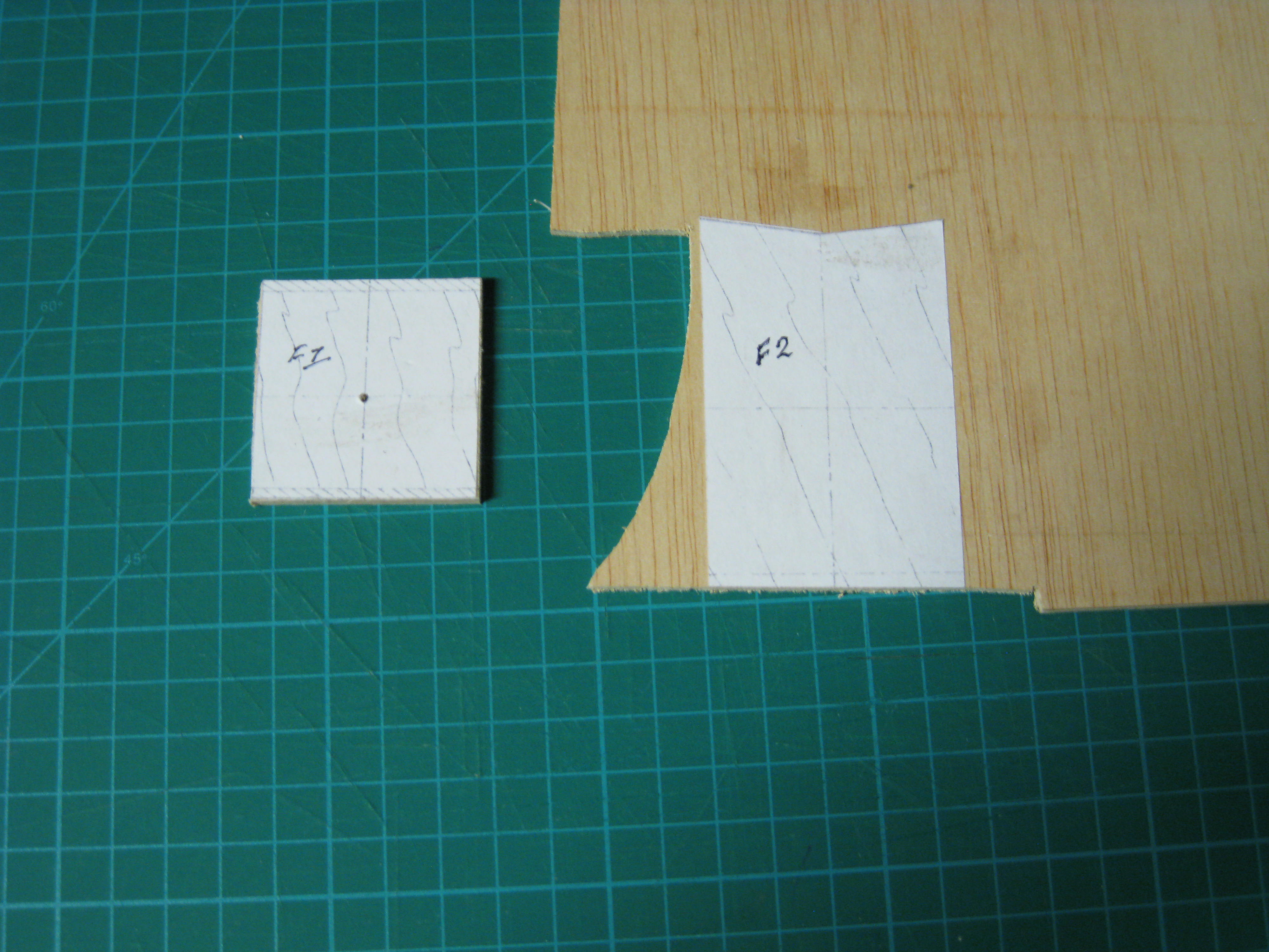 Drill a small hole in the centre of F1. This will help to align the motor.
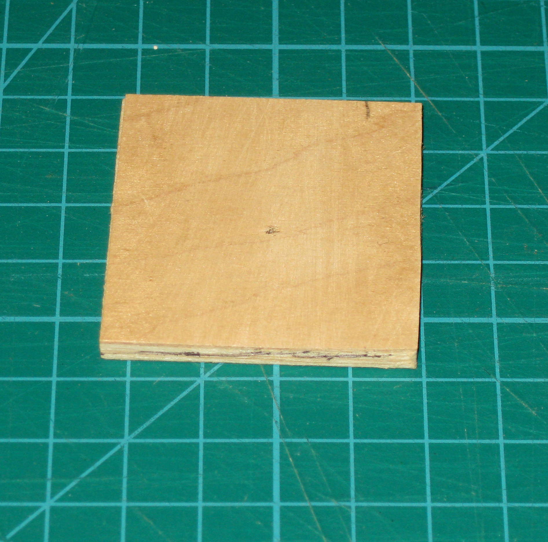
As this is an electric model, rather than use 6mm ply for F1 I laminated a piece of 3mm balsa with 1.5mm ply on each side.
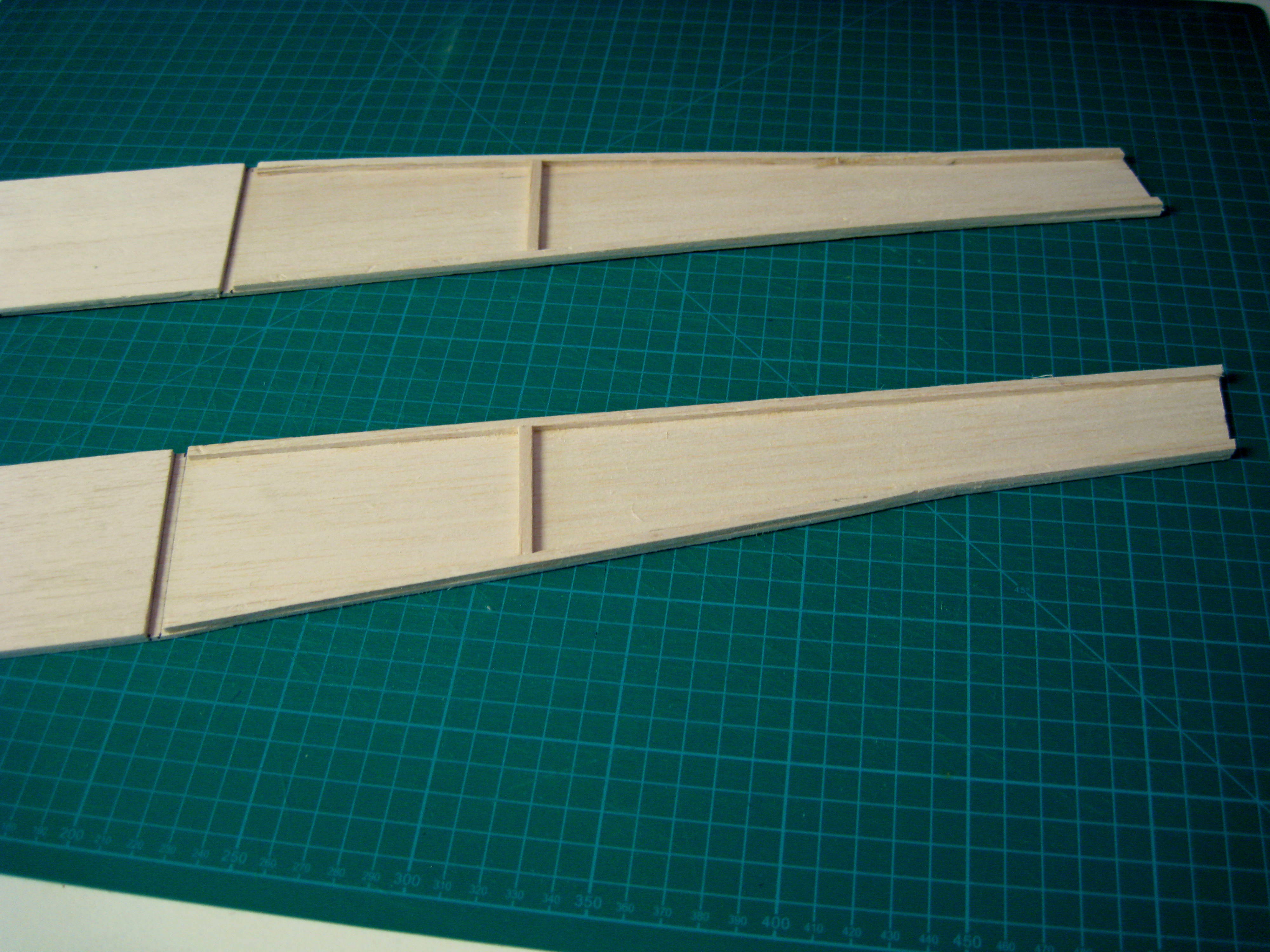
Glue a sheet of balsa to the fuselage sides to create the doubler. It runs from in front of F4 to the nose. Make sure to make a right hand and left hand side!
 When its dry, cut around the fuselage side.
—————————————————————————————————————————————————–
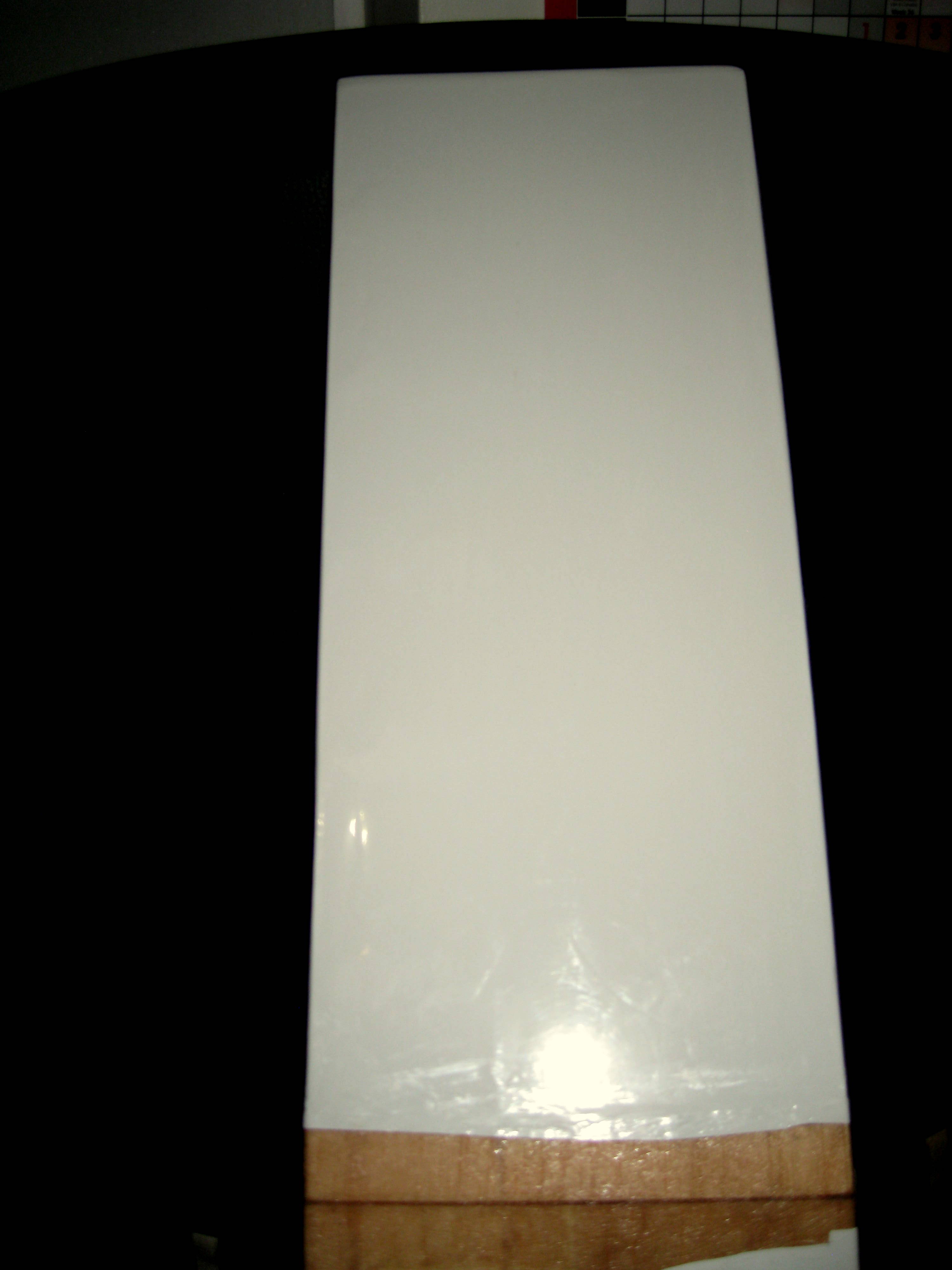
Print the tailplane template.
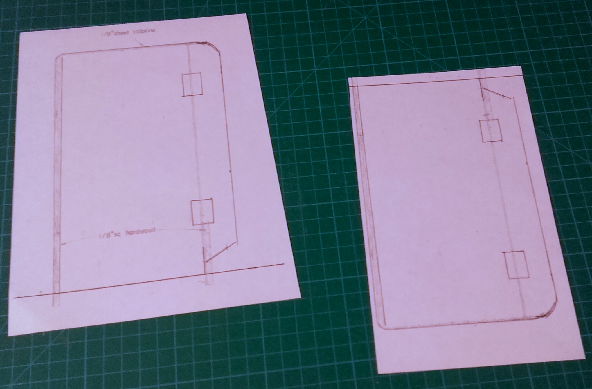 Trim along the centre line and join them together.
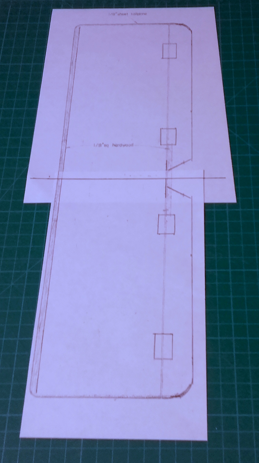 Stick the completed template to a balsa sheet and cut along the outline.
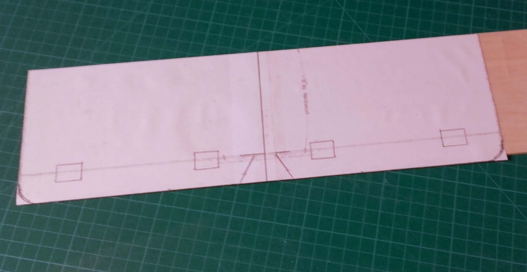 Cut off the elevator. DO NOT cut out the “V” in the centre.
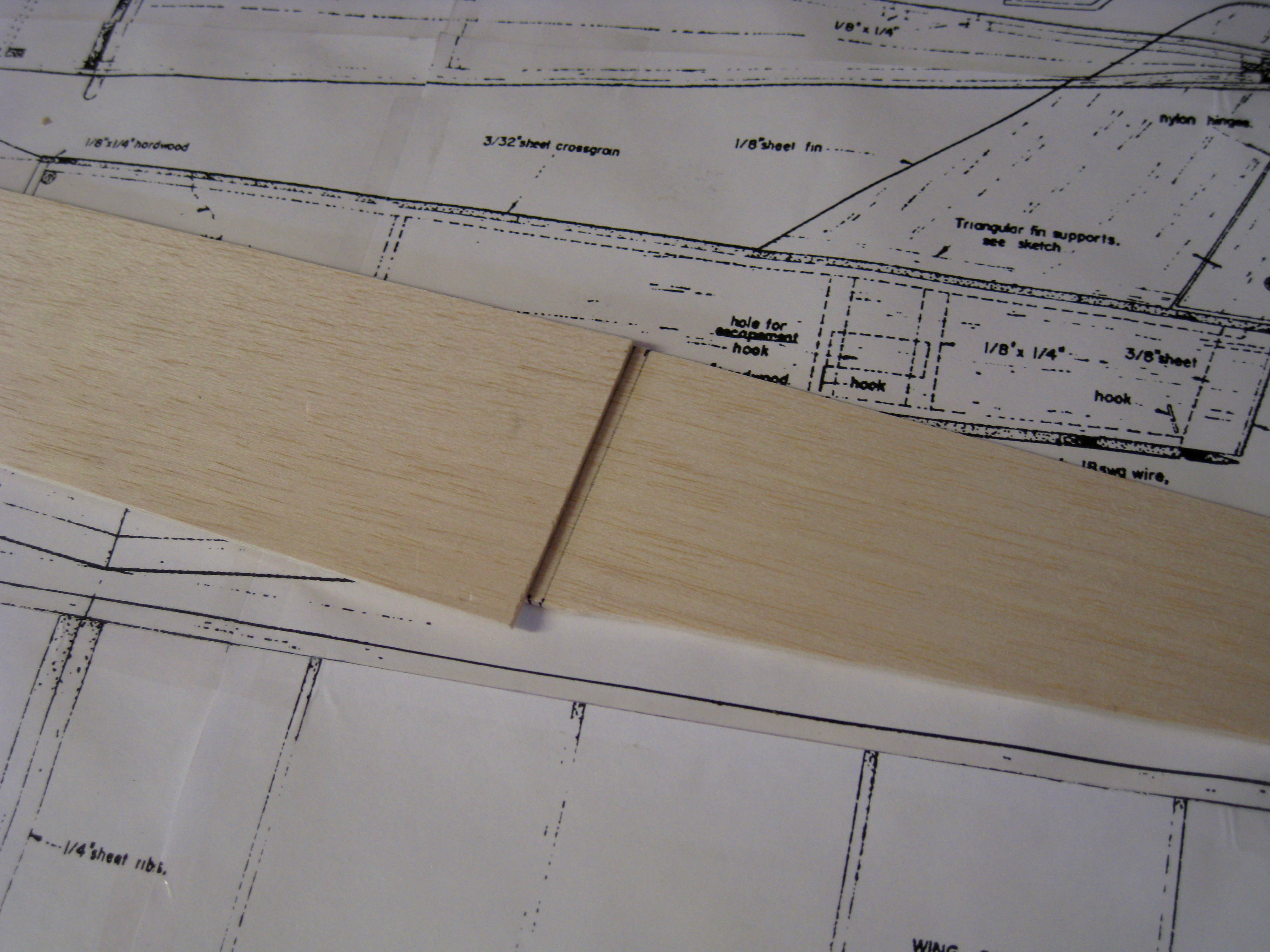
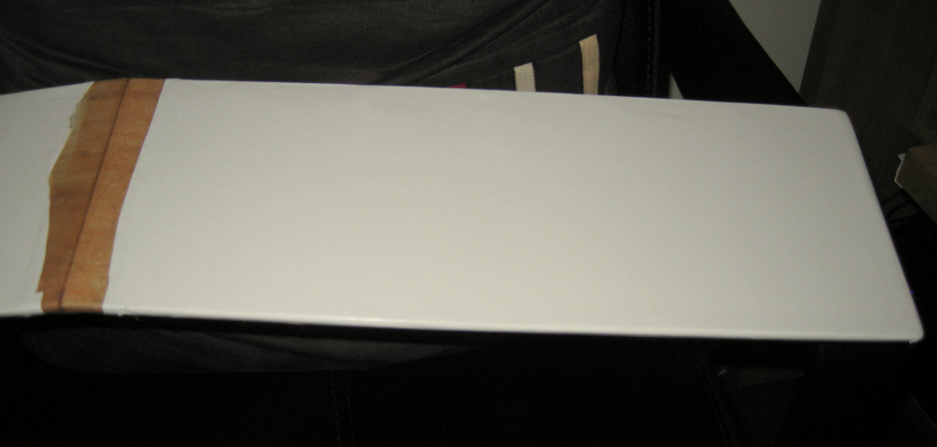
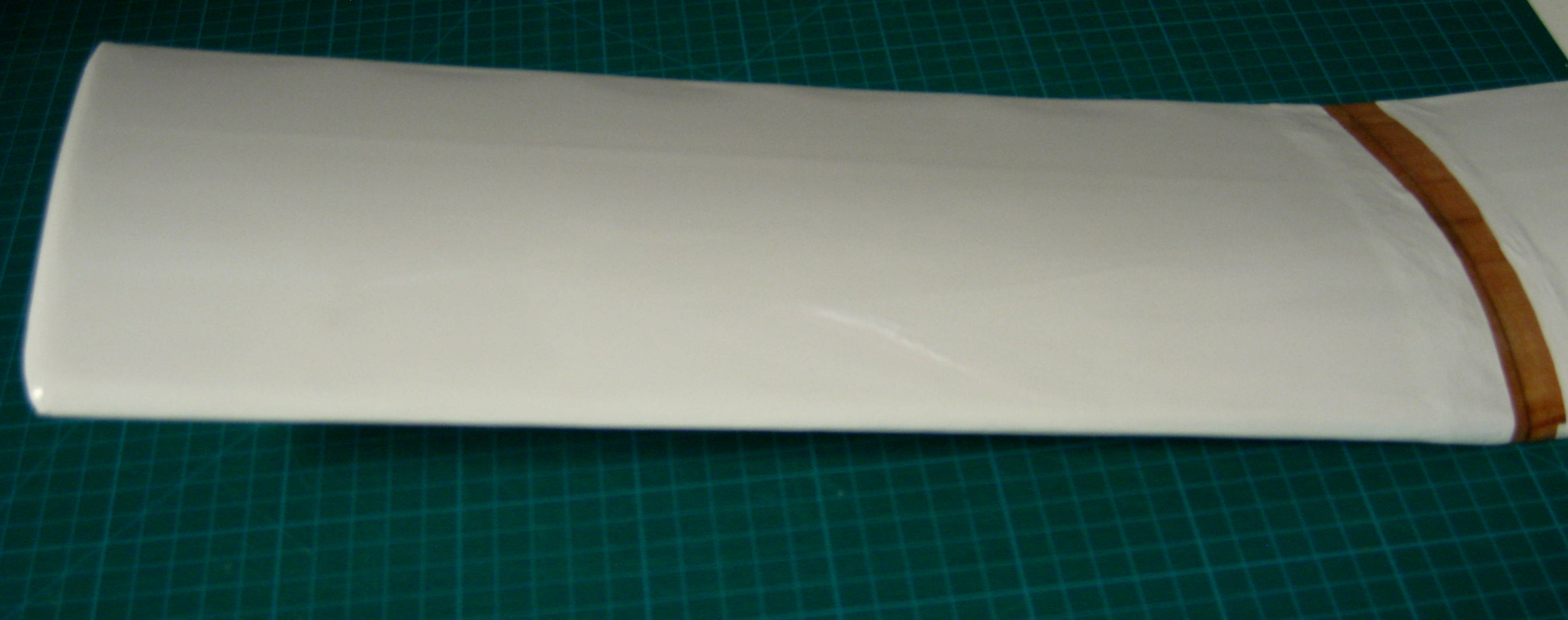
 Glue a piece of 3mm hardwood strip to the leading edges. This helps to prevent warps when covering.
 Cut out the fin in the same way.
—————————————————————————————————————————————————-
Now you have a complete set of parts and the real building can begin.
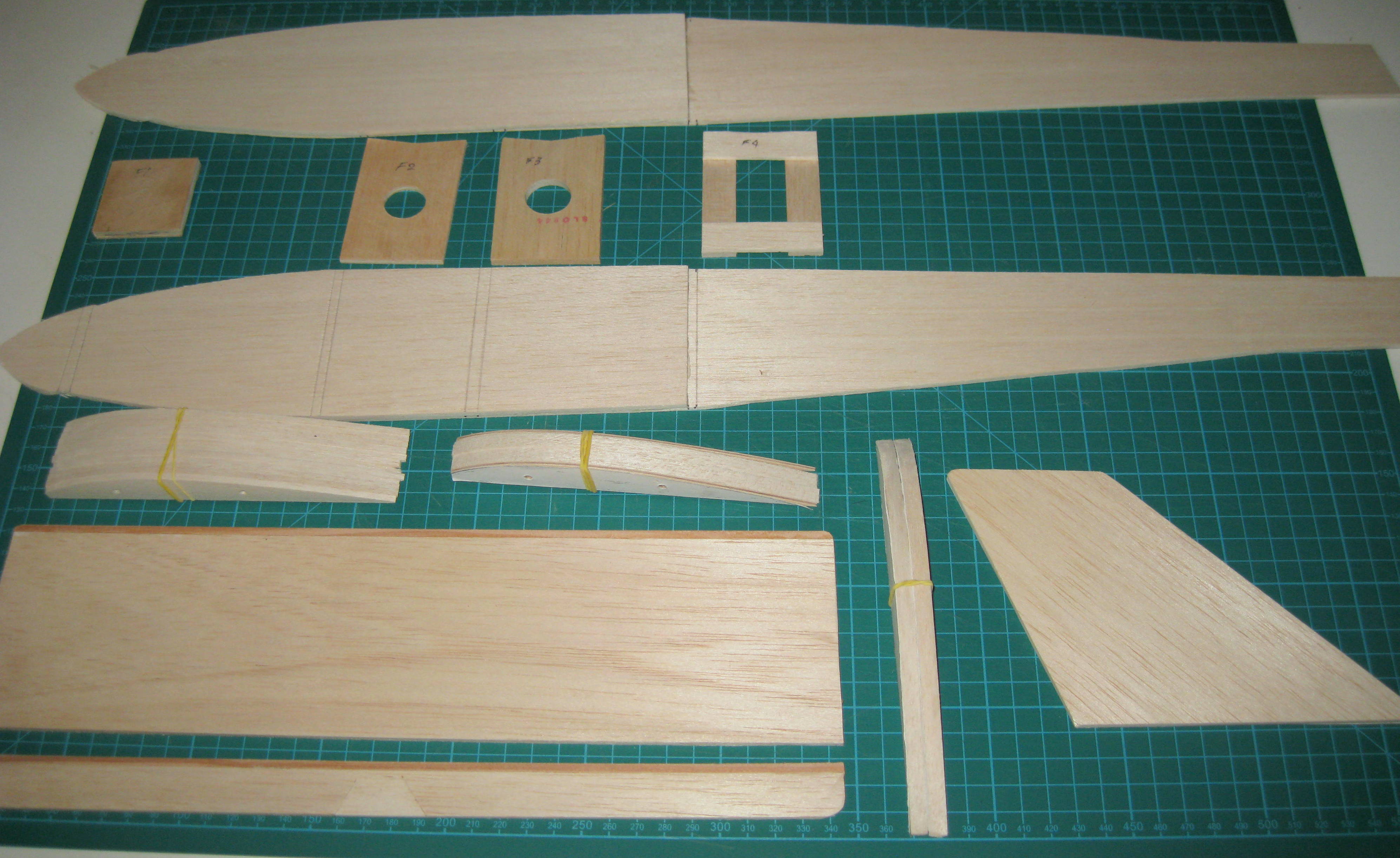
—————————————————————————————————————————————————–
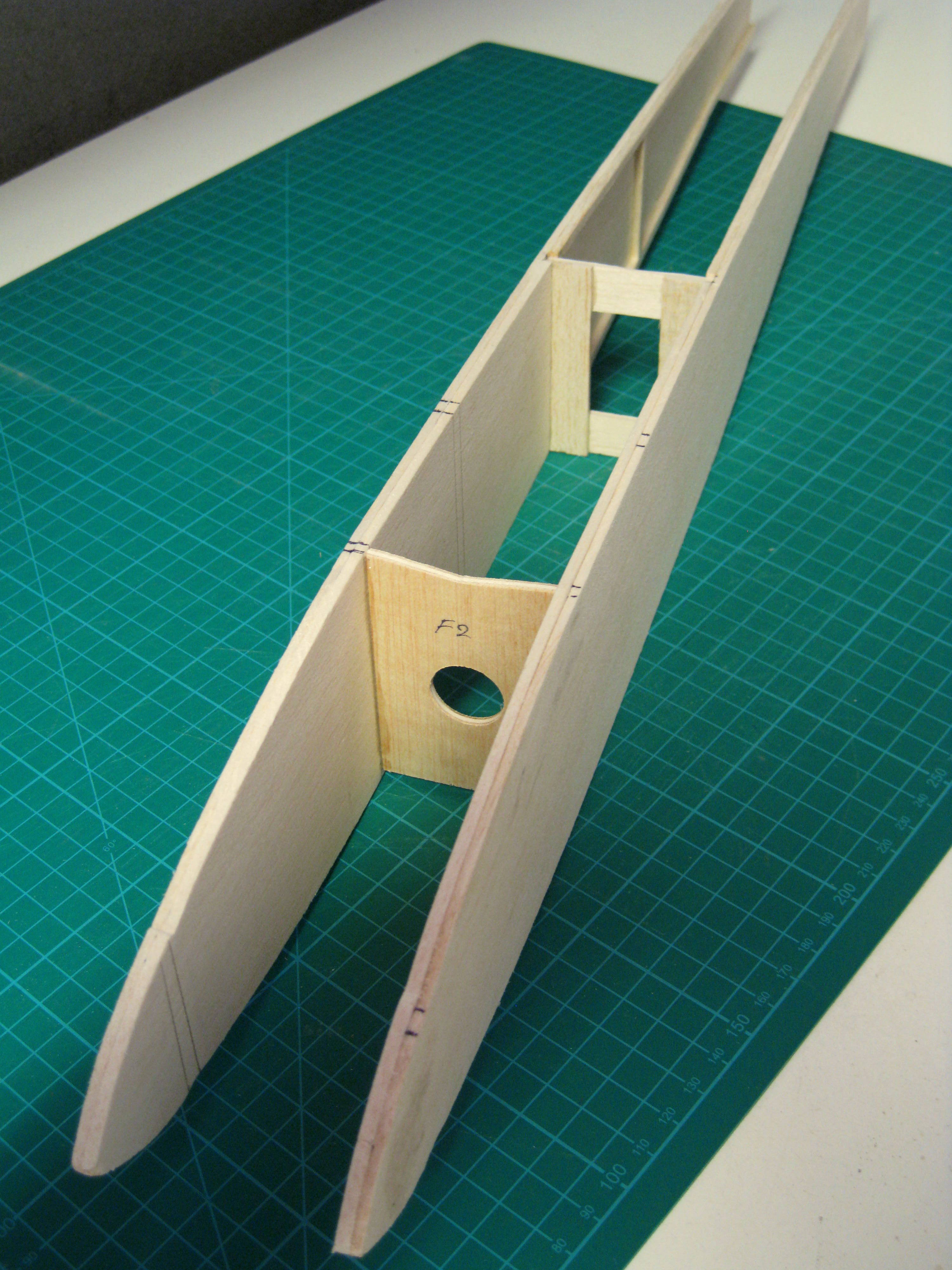
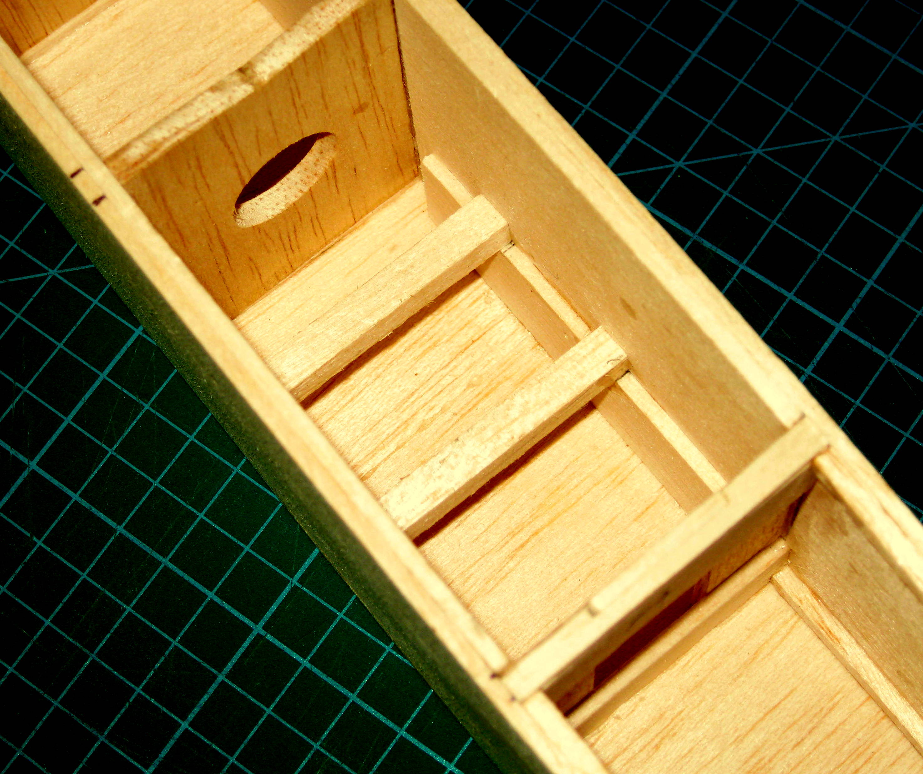
Glue the longerons, (wood strips), to the fuselage sides, leaving a gap for F4.
 Glue F2 and F4 in position making sure that they are square.
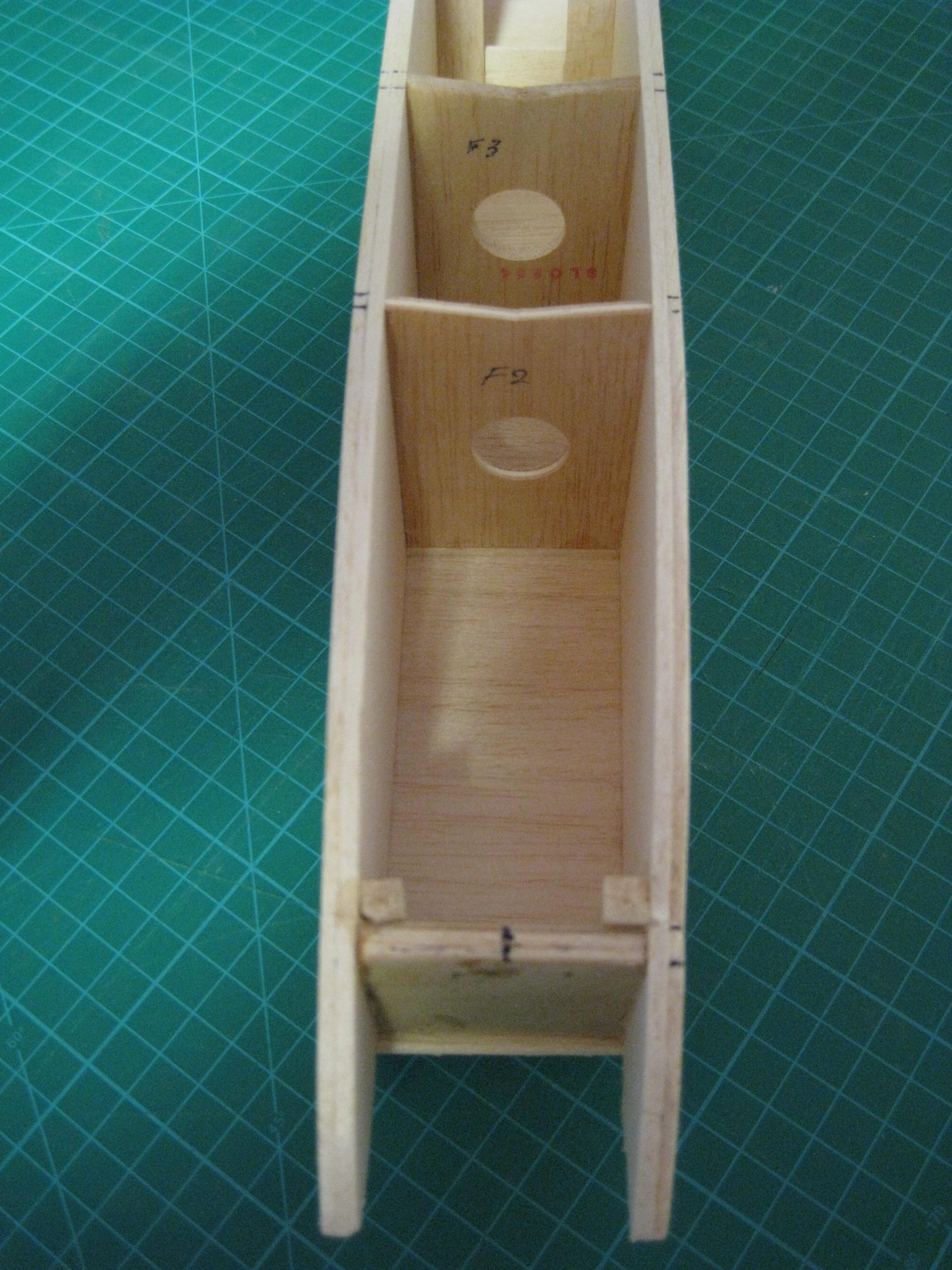
 When dry, attach the other fuselage side
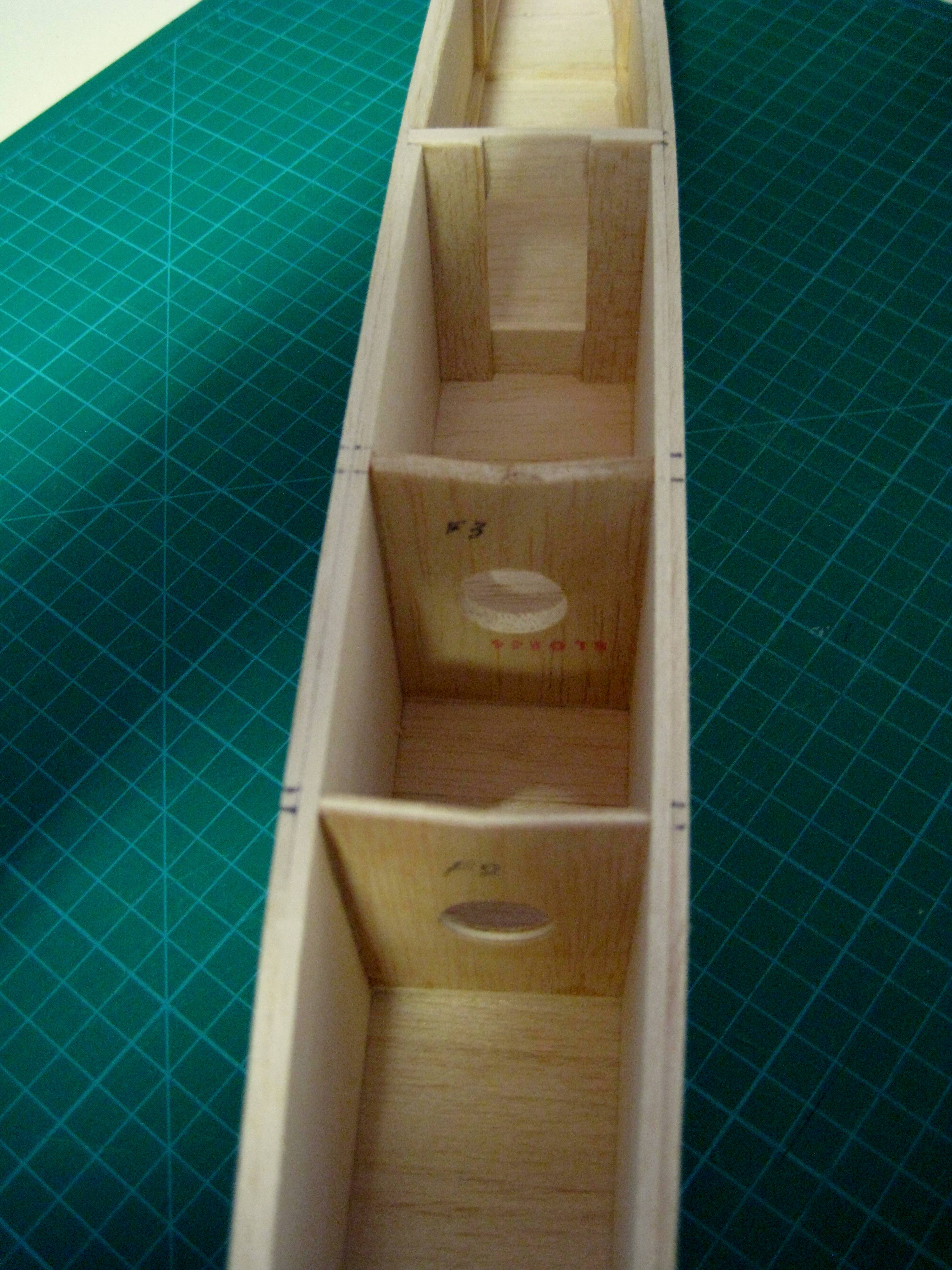
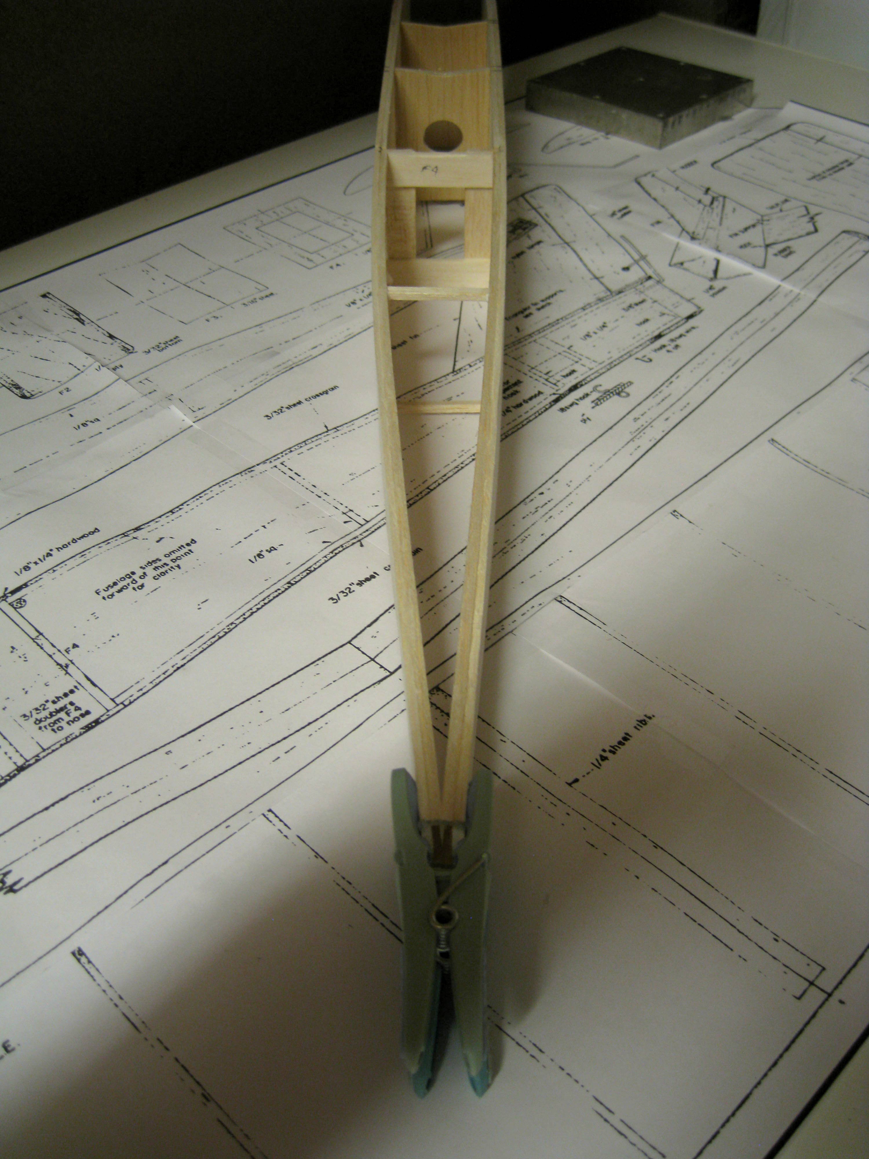
 .Fit F3 and pull the nose together to attach F1.
 Glue the tail together and add the cross pieces.
 Now add the bottom cross grain sheeting.
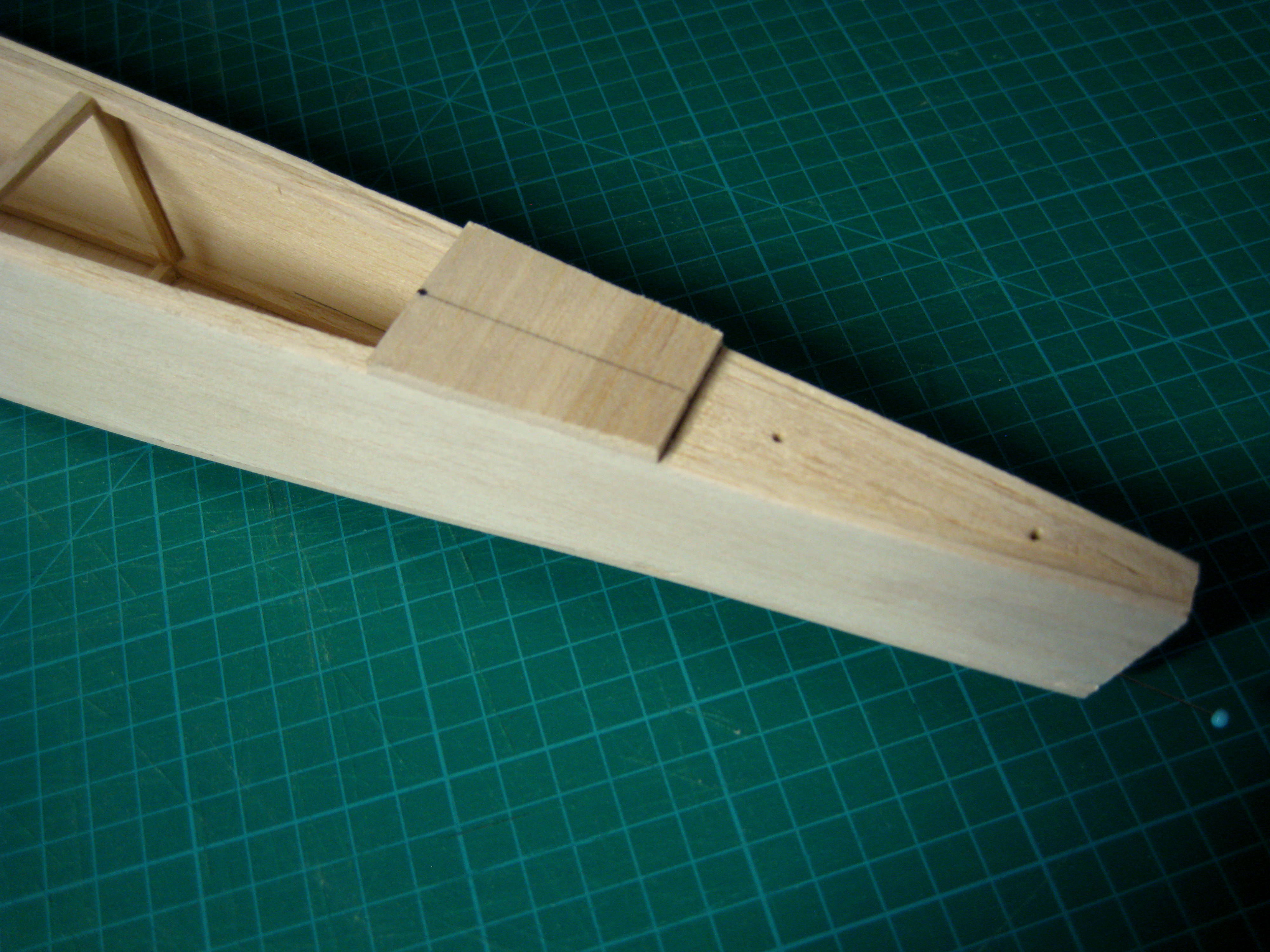
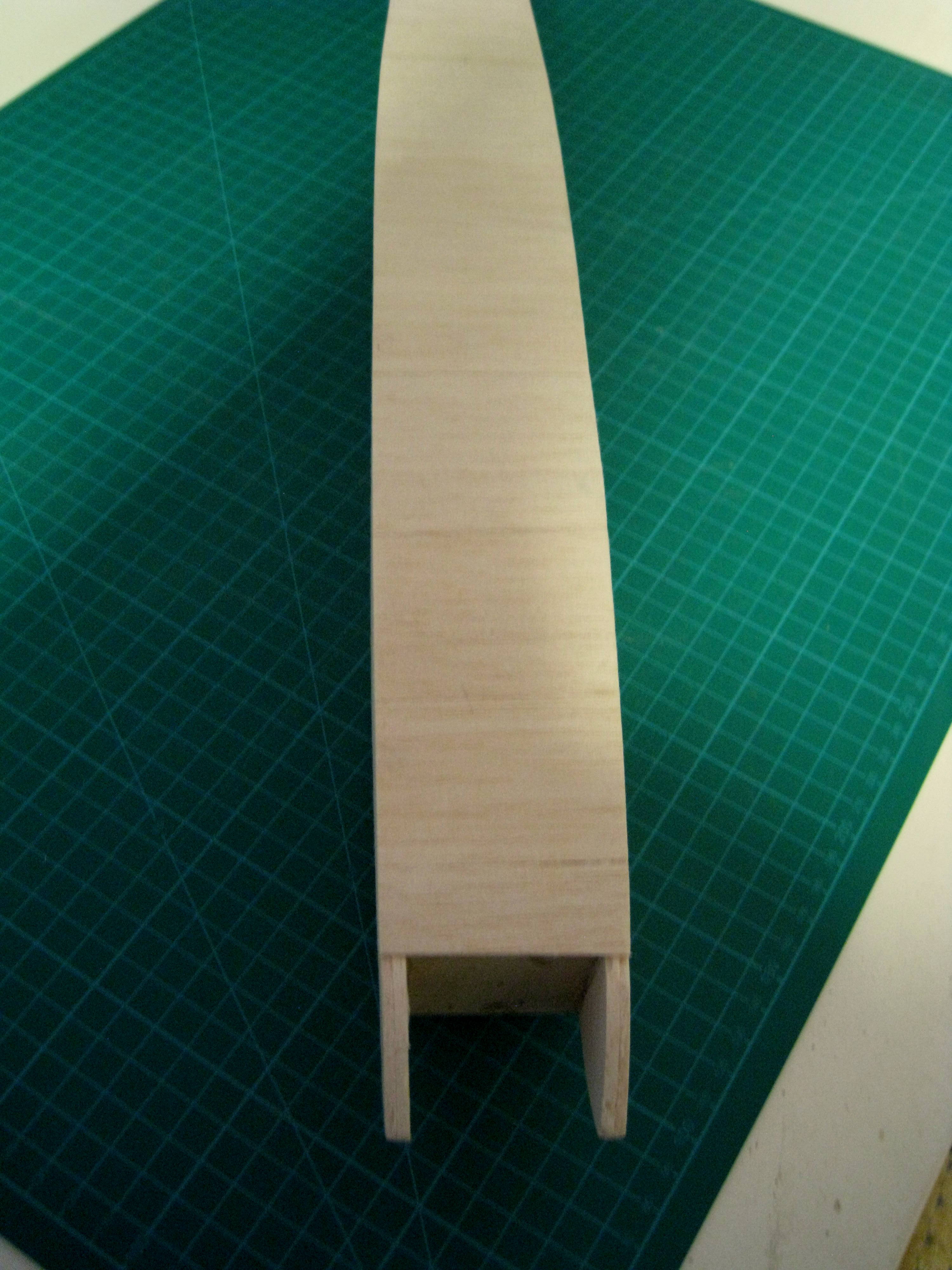 Build up a platform for the tailplane and mark the centre line.
—————————————————————————————————————————————————–
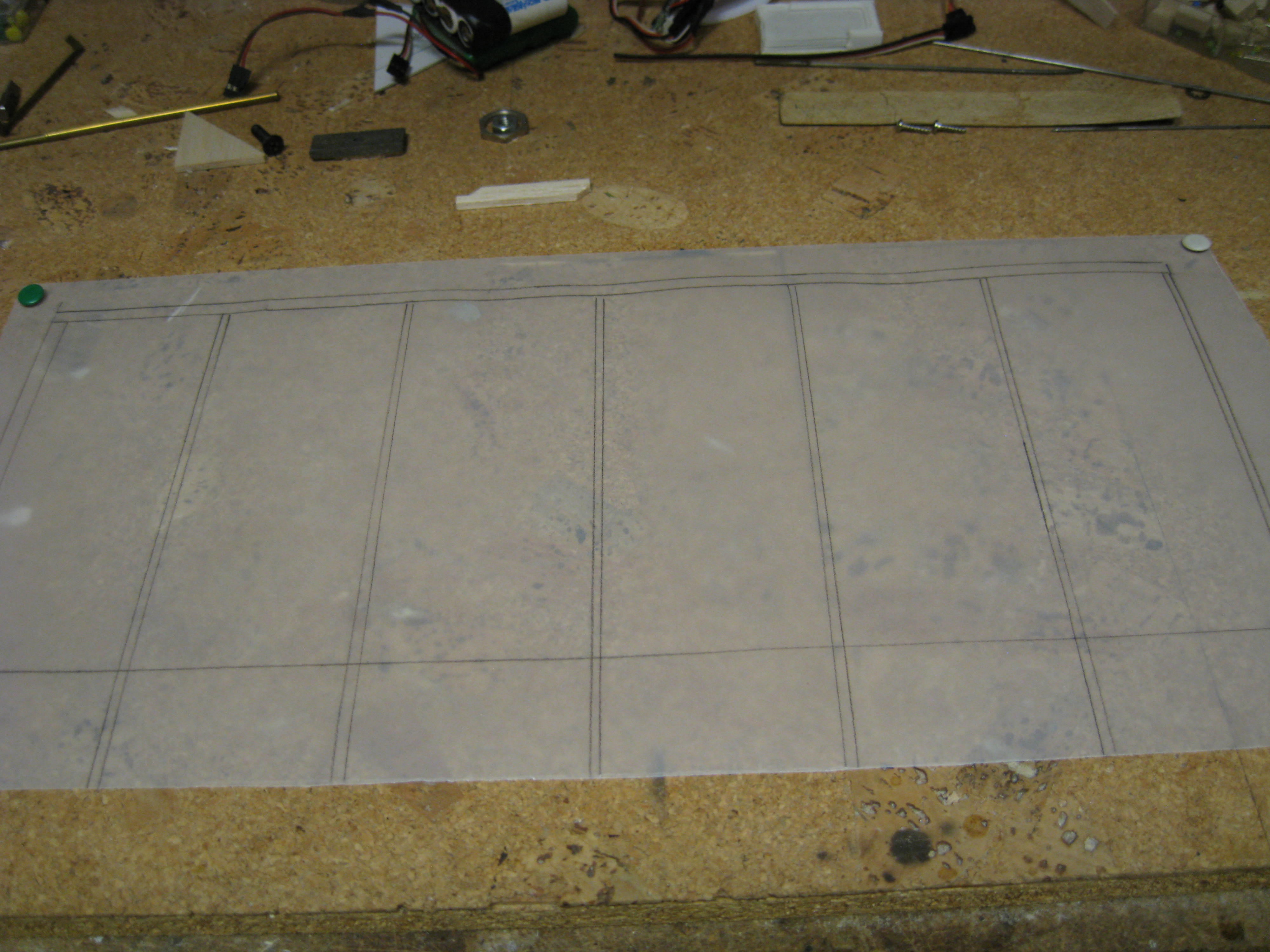
Trace the wing. Extend the rib positions beyond the trailing edge.
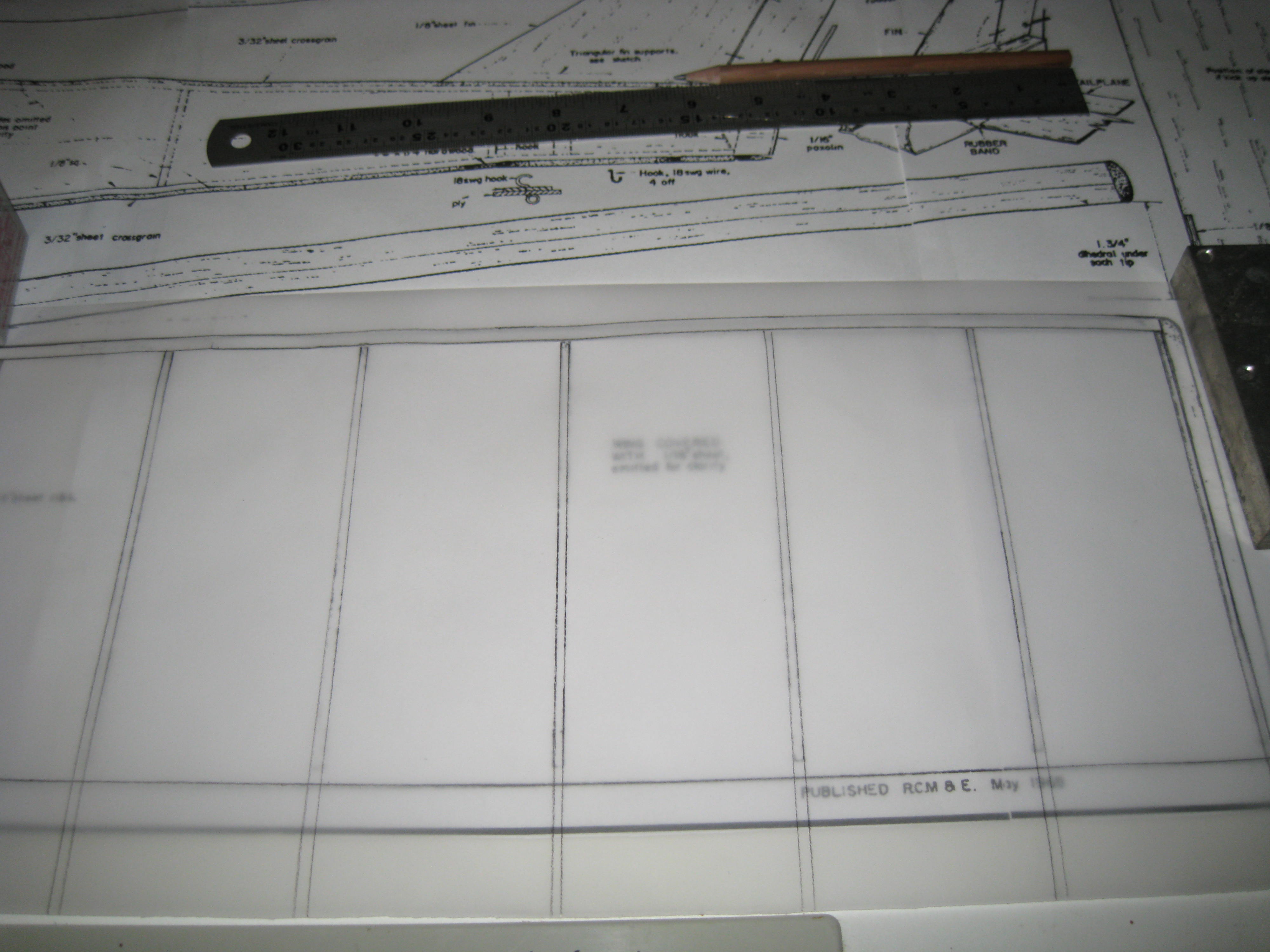 Pin the tracing to the building board.
 Cut the pieces of wing sheeting slightly oversize.
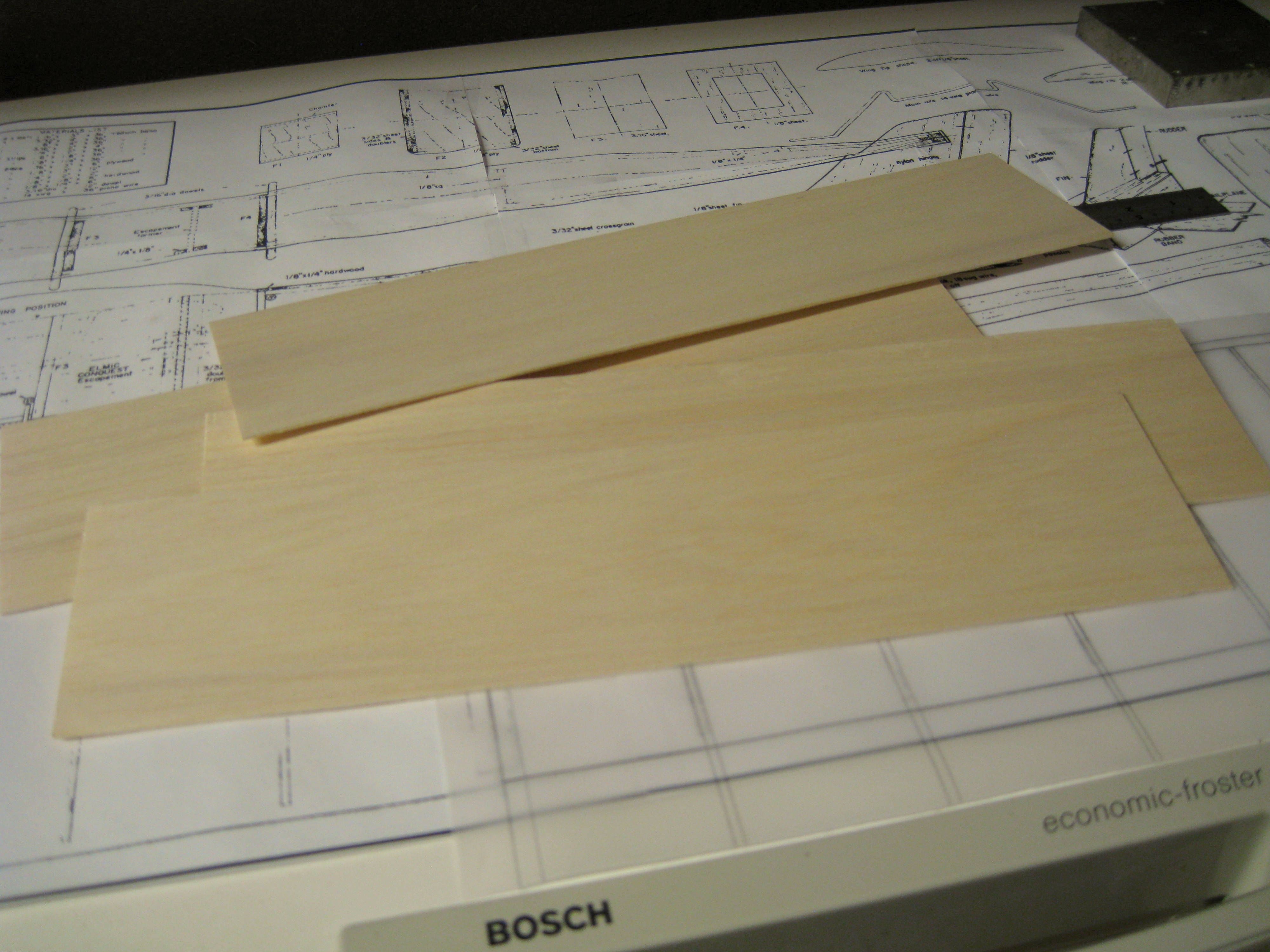
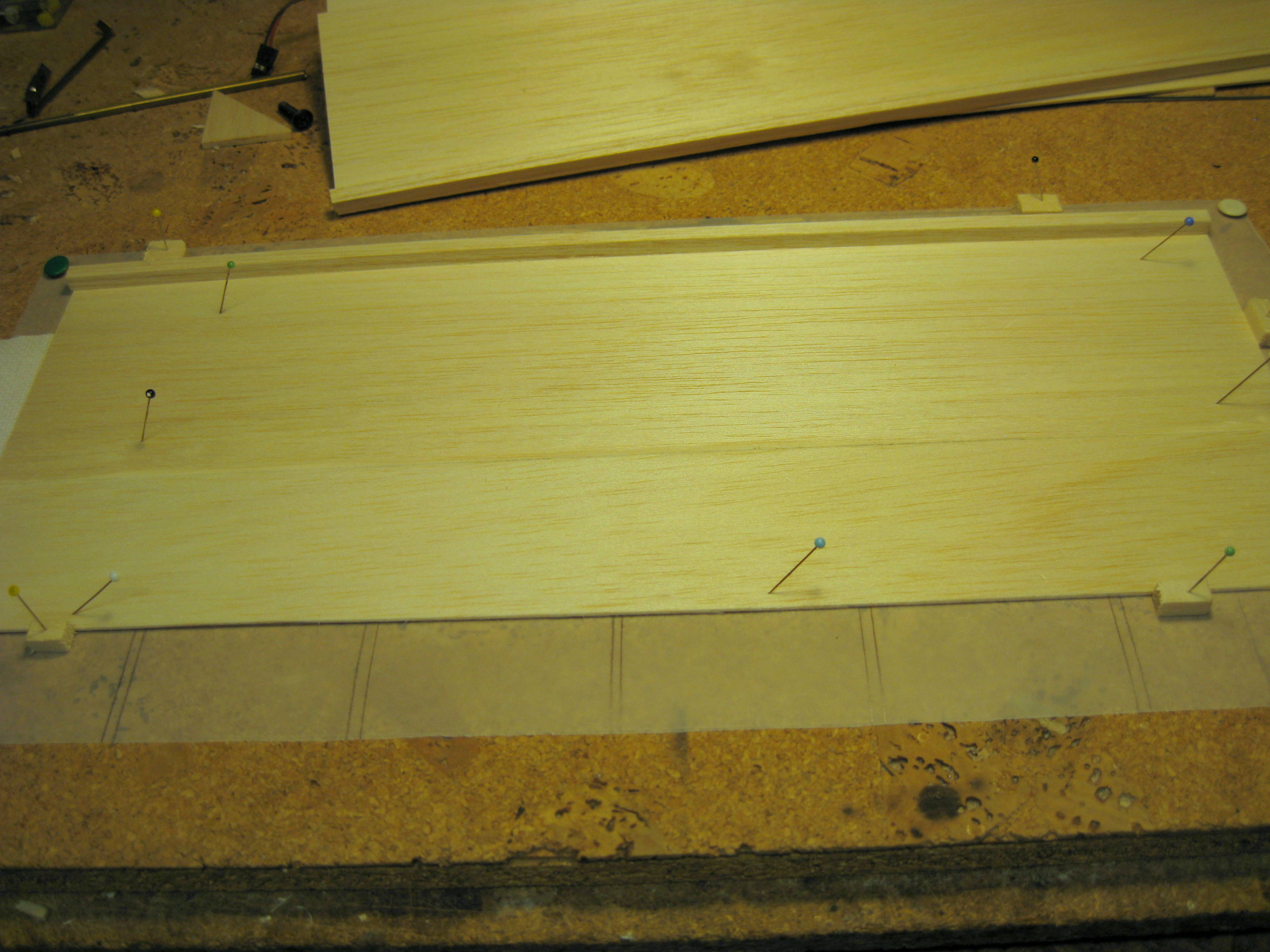
Glue the leading edge strip to the sheet. Pin it down in position and cut the rear sheet to size. Use small balsa blocks pinned to the building board to aid location.
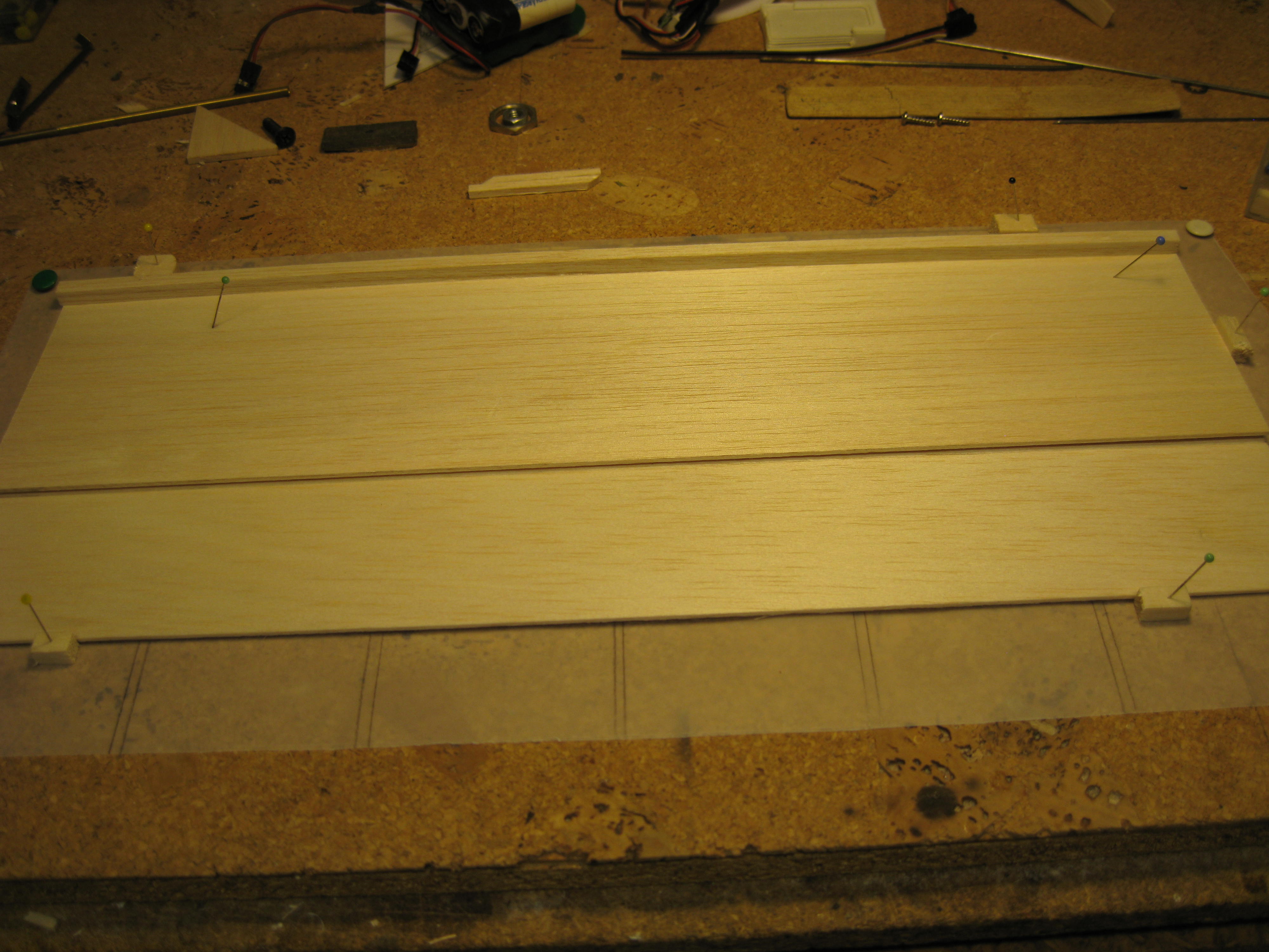 Edge glue the two sheets together keeping them both flat.
 Glue the wing ribs, except for the root rib, into position.
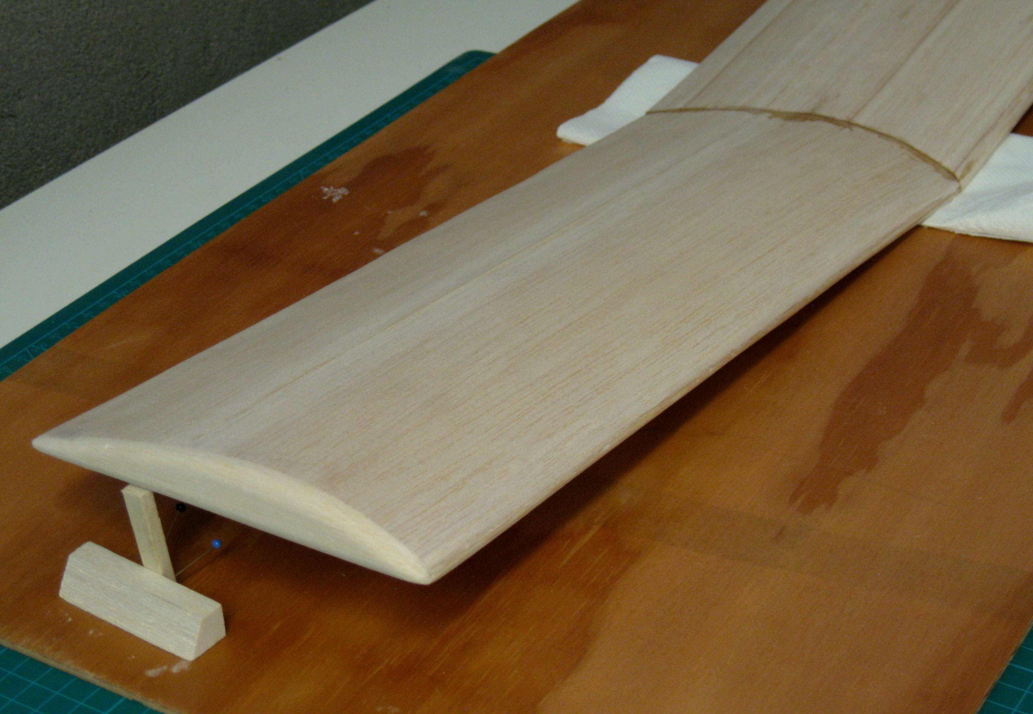
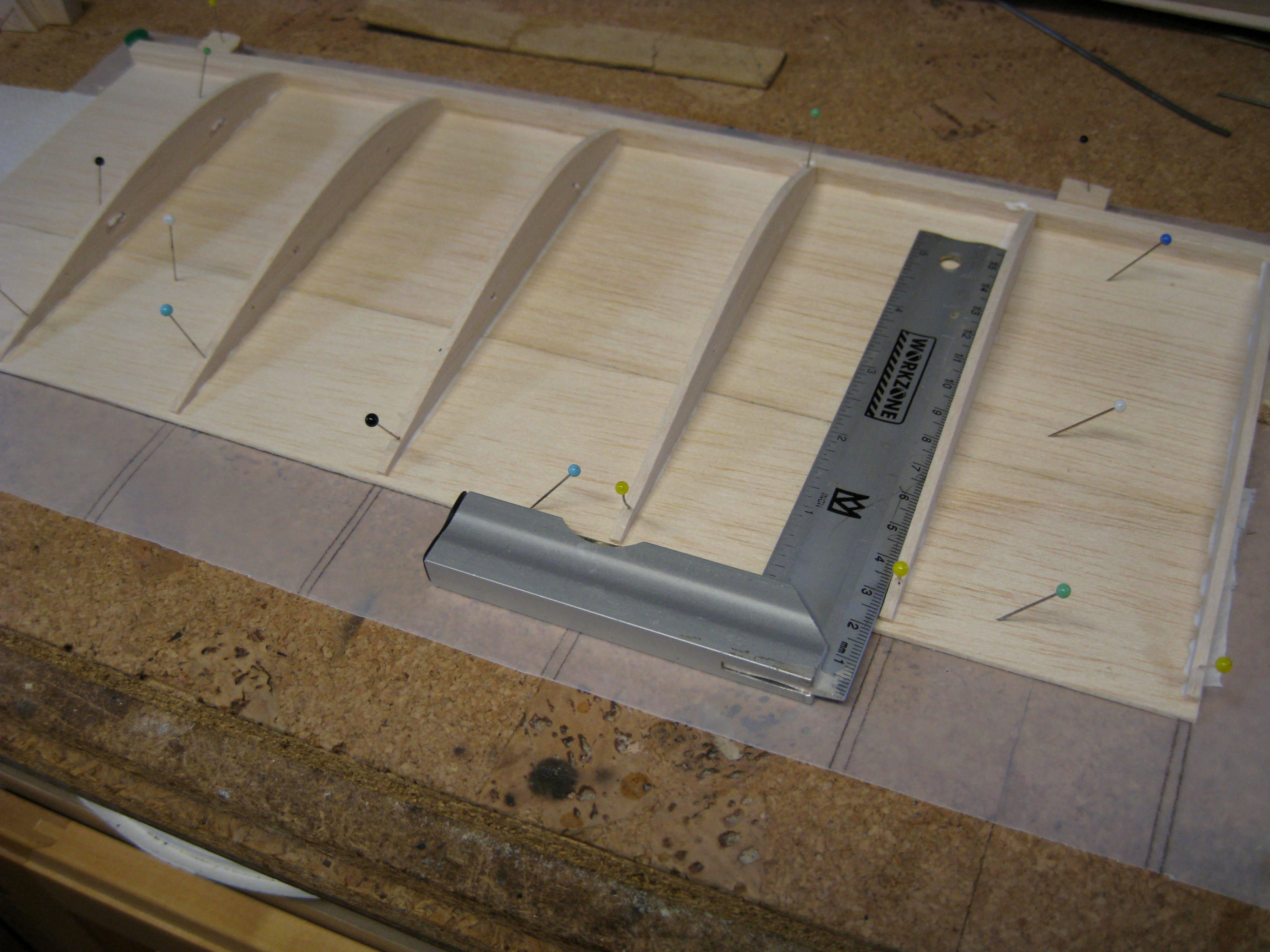 To set the root rib at the correct angle, first make a support 1 3/4″ (44mm) high.
(Make two, you’ll need them at the wing joining stage)
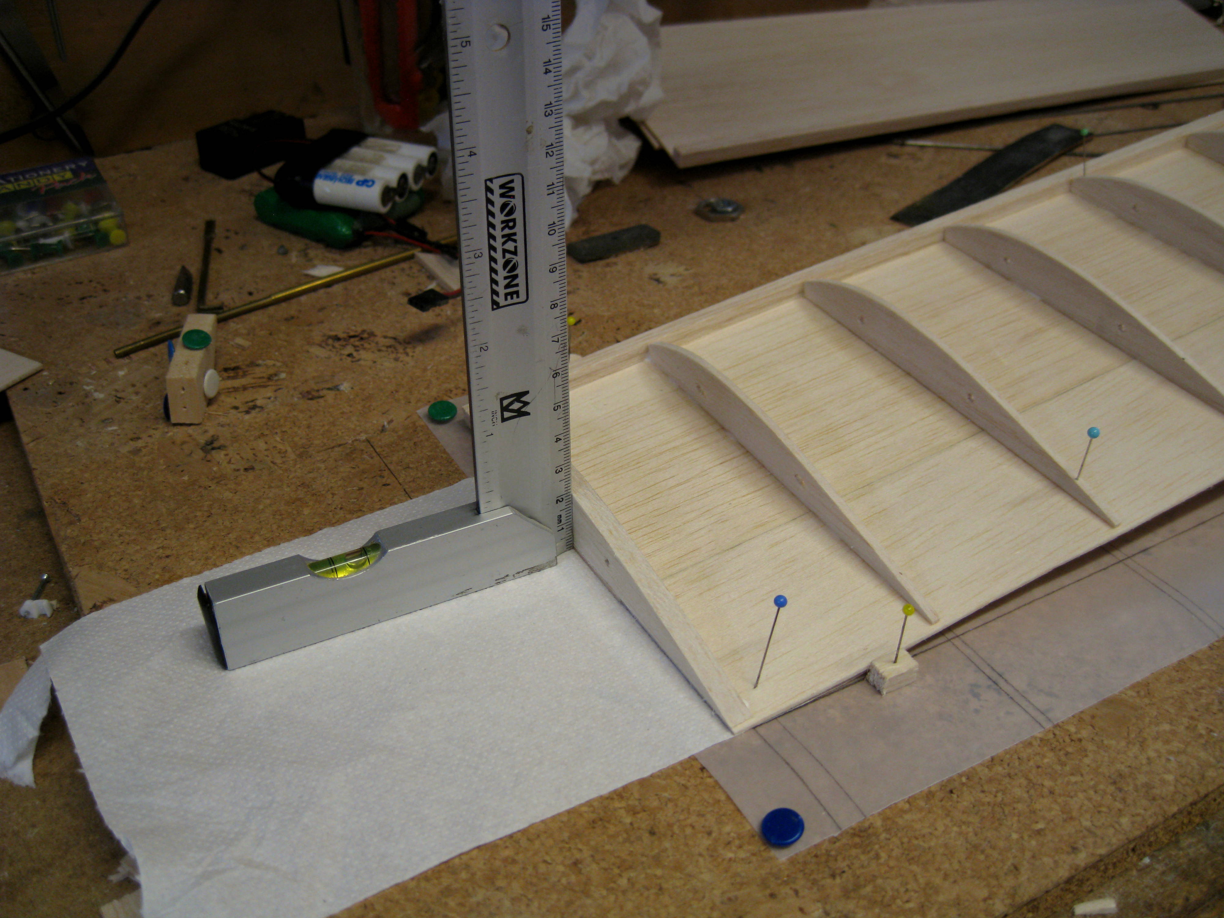
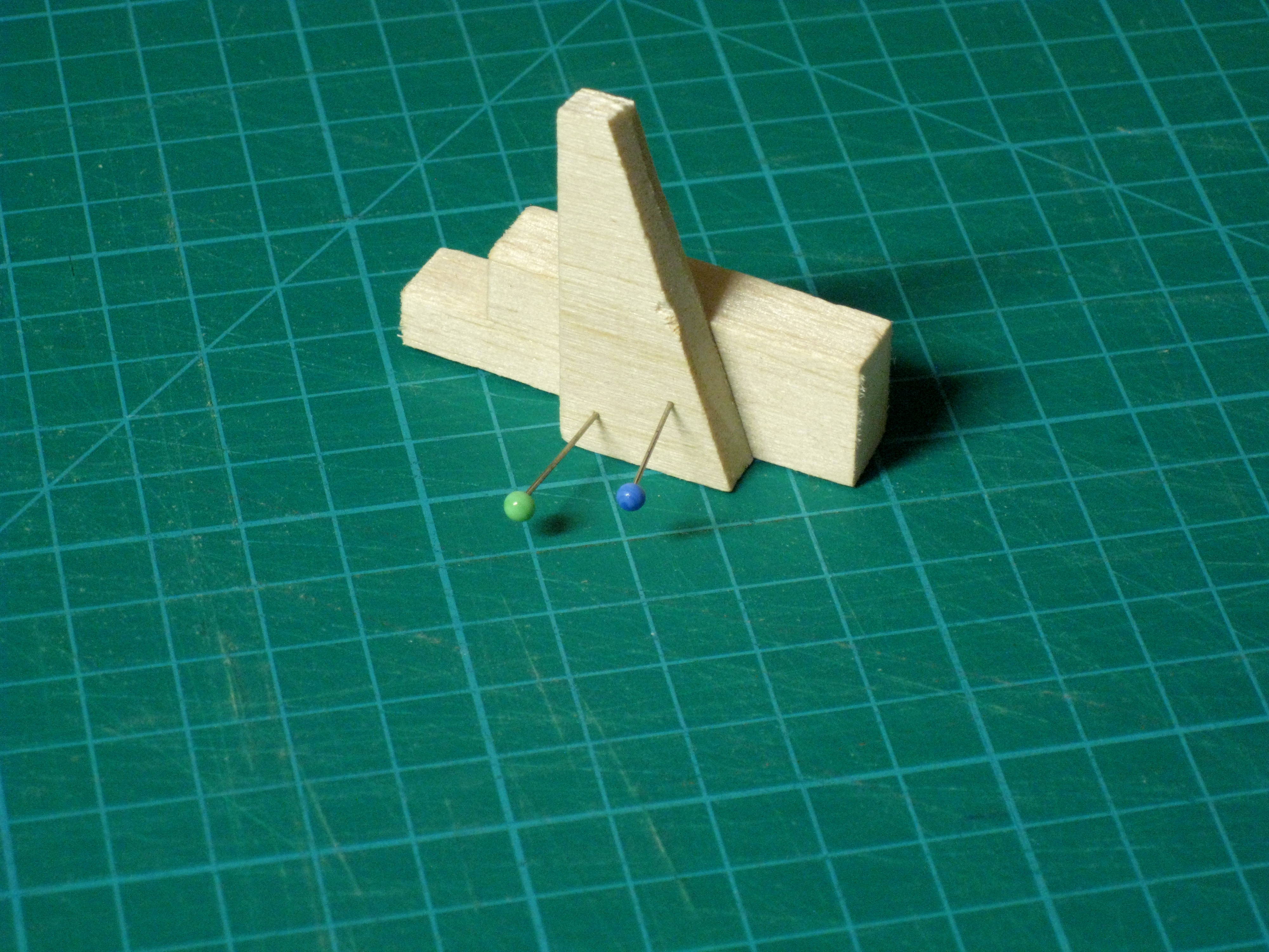 Place the support under the wing tip.
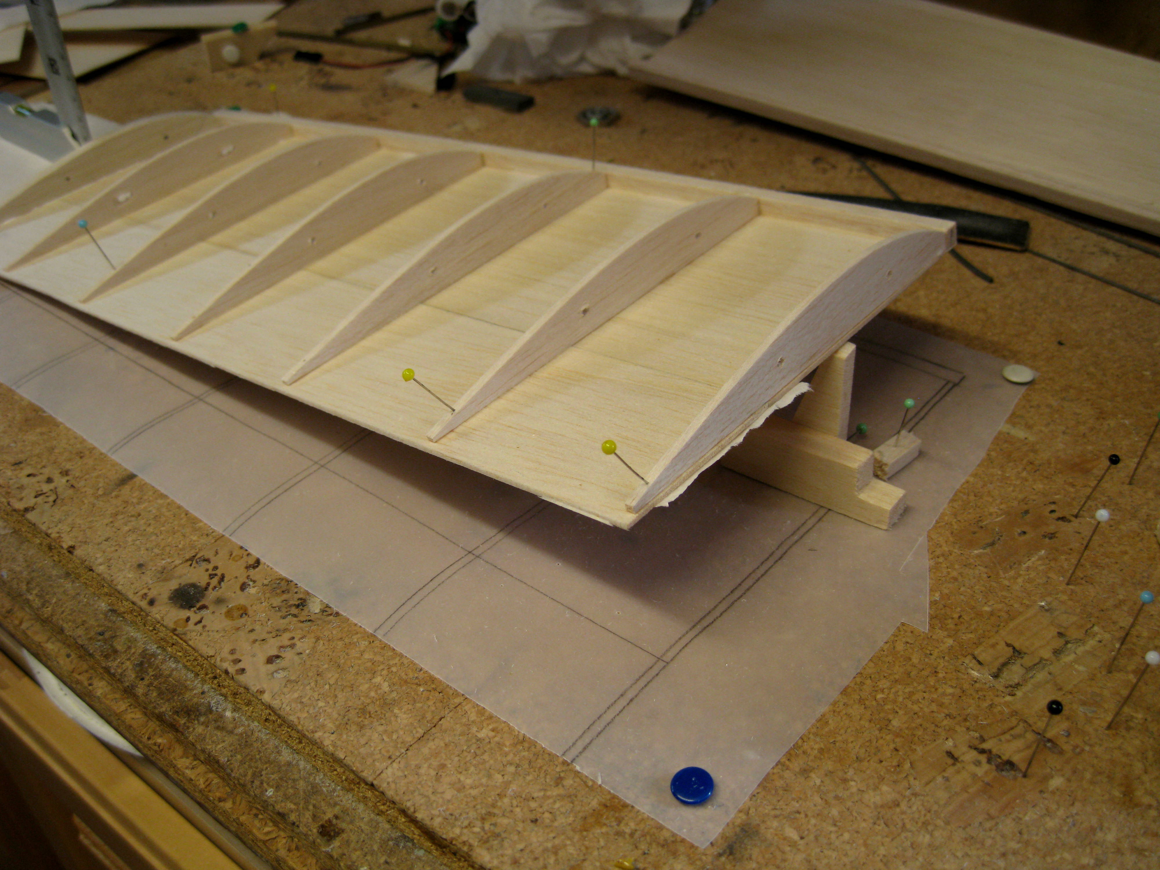 Set the root rib at right angles to the building board.
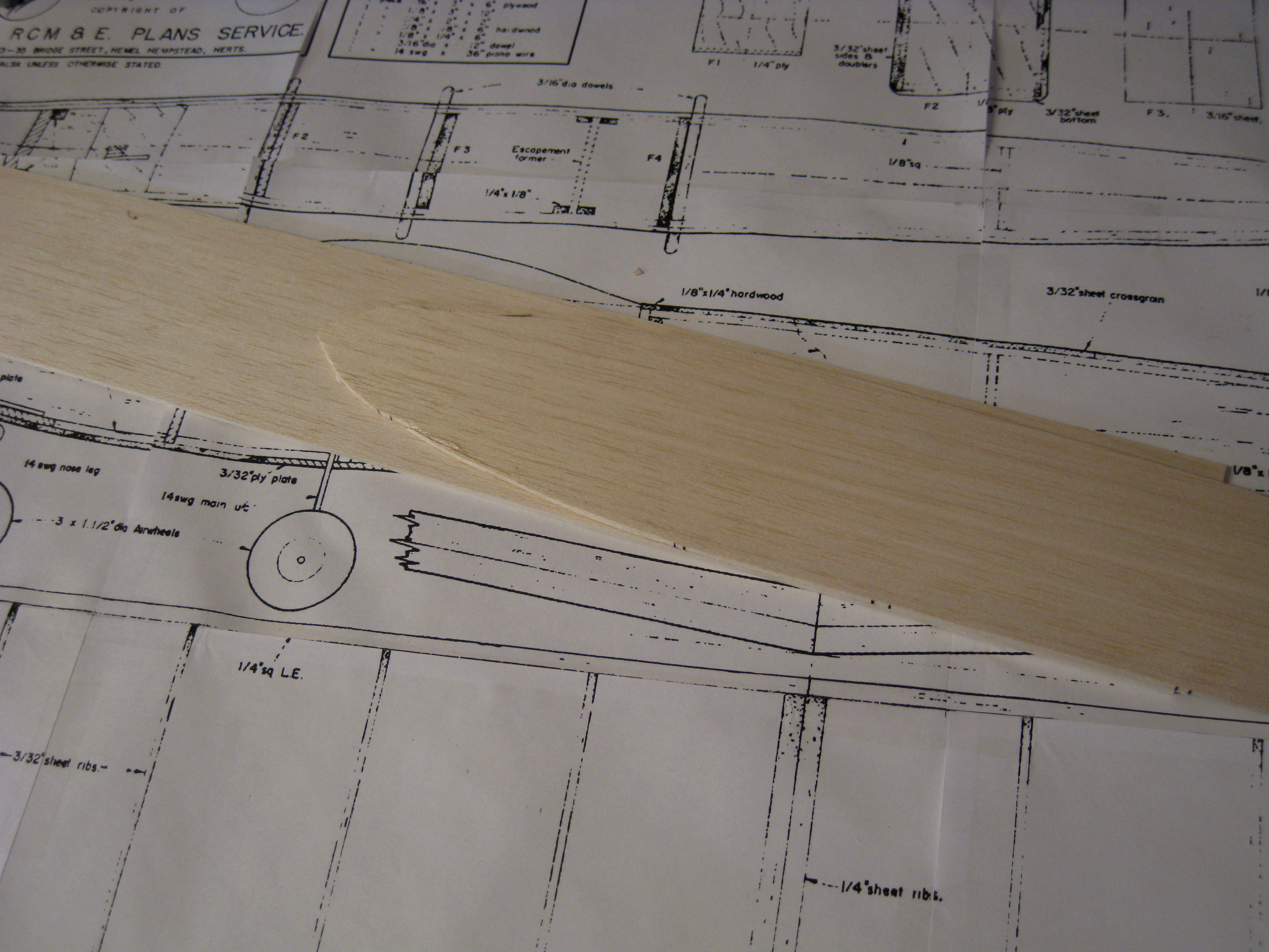
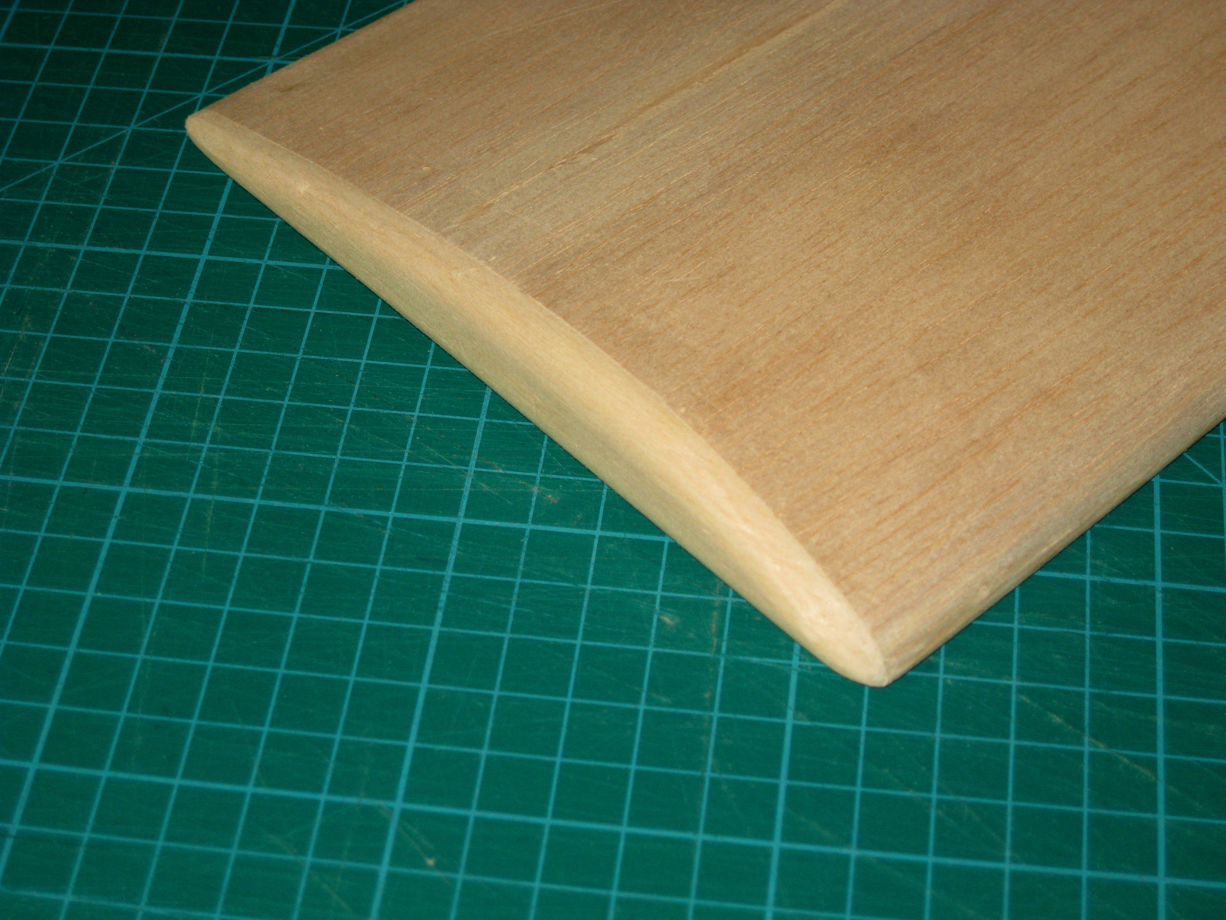
 Shape the leading edge to continue the rib profile.
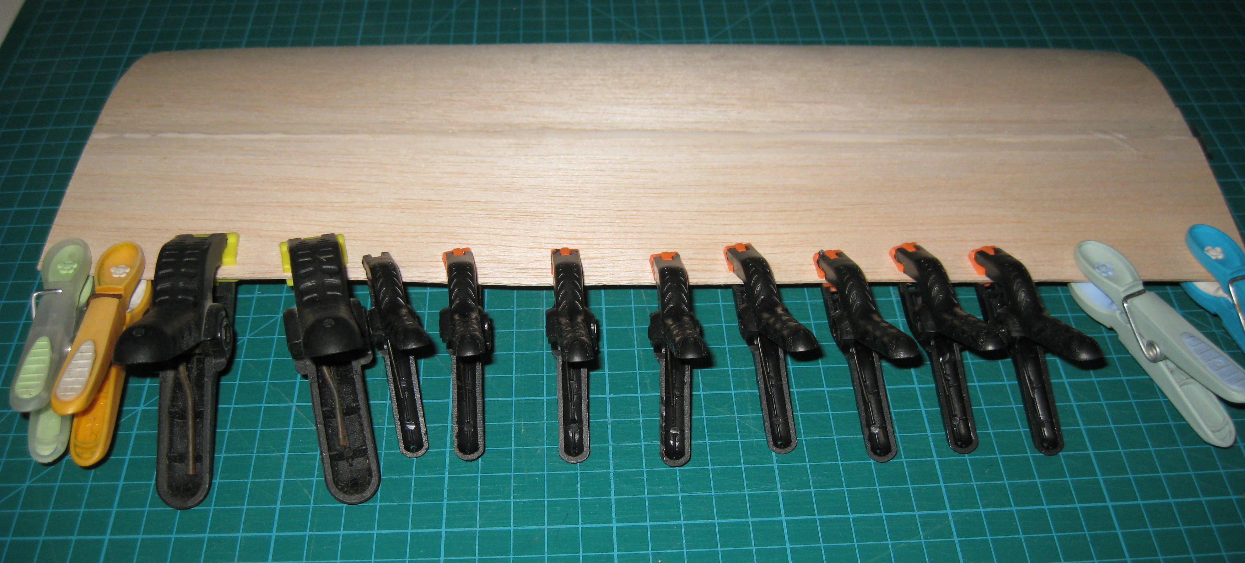
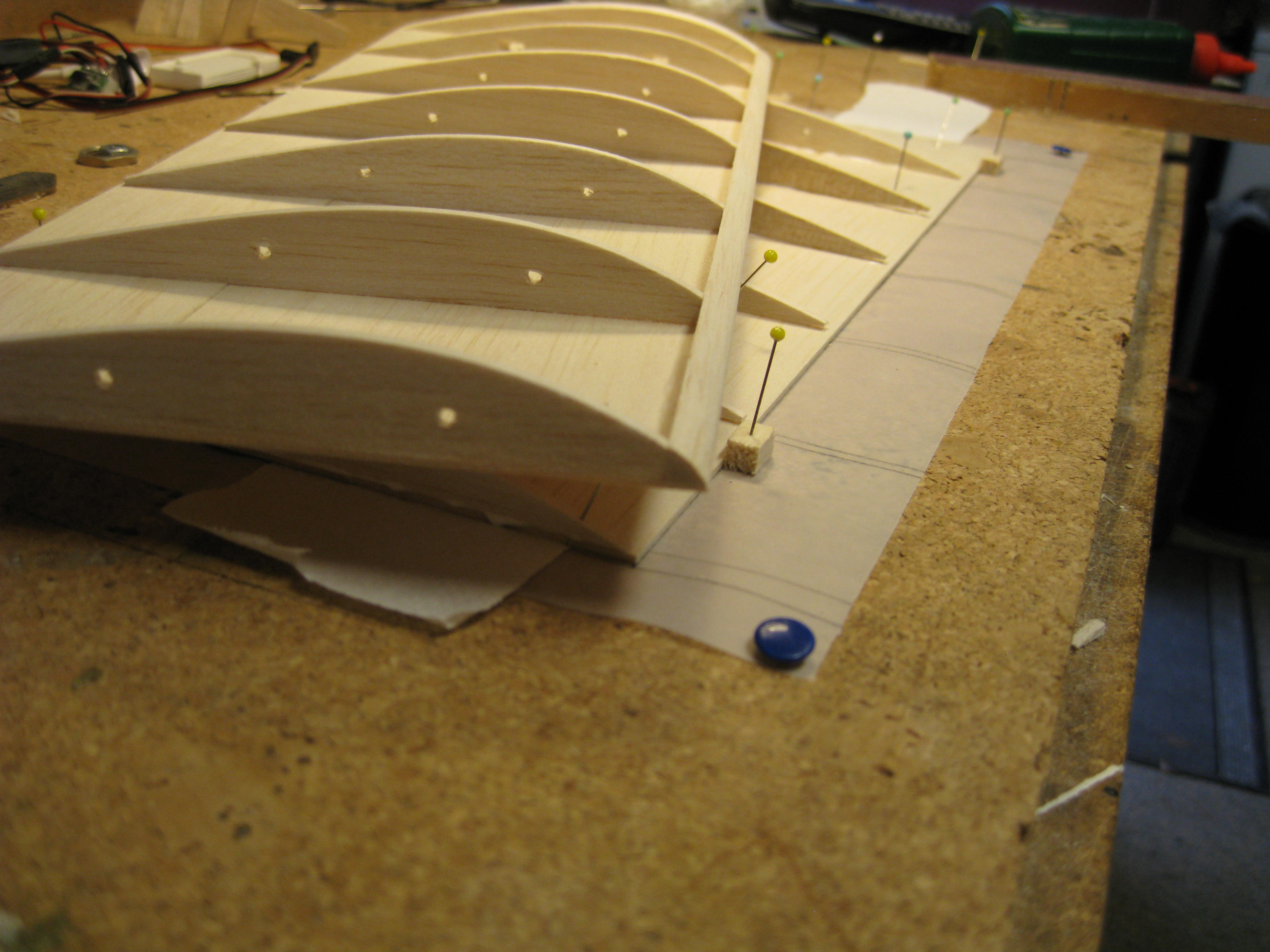 Attach the leading edge top sheeting. Clamp and pin it in place.
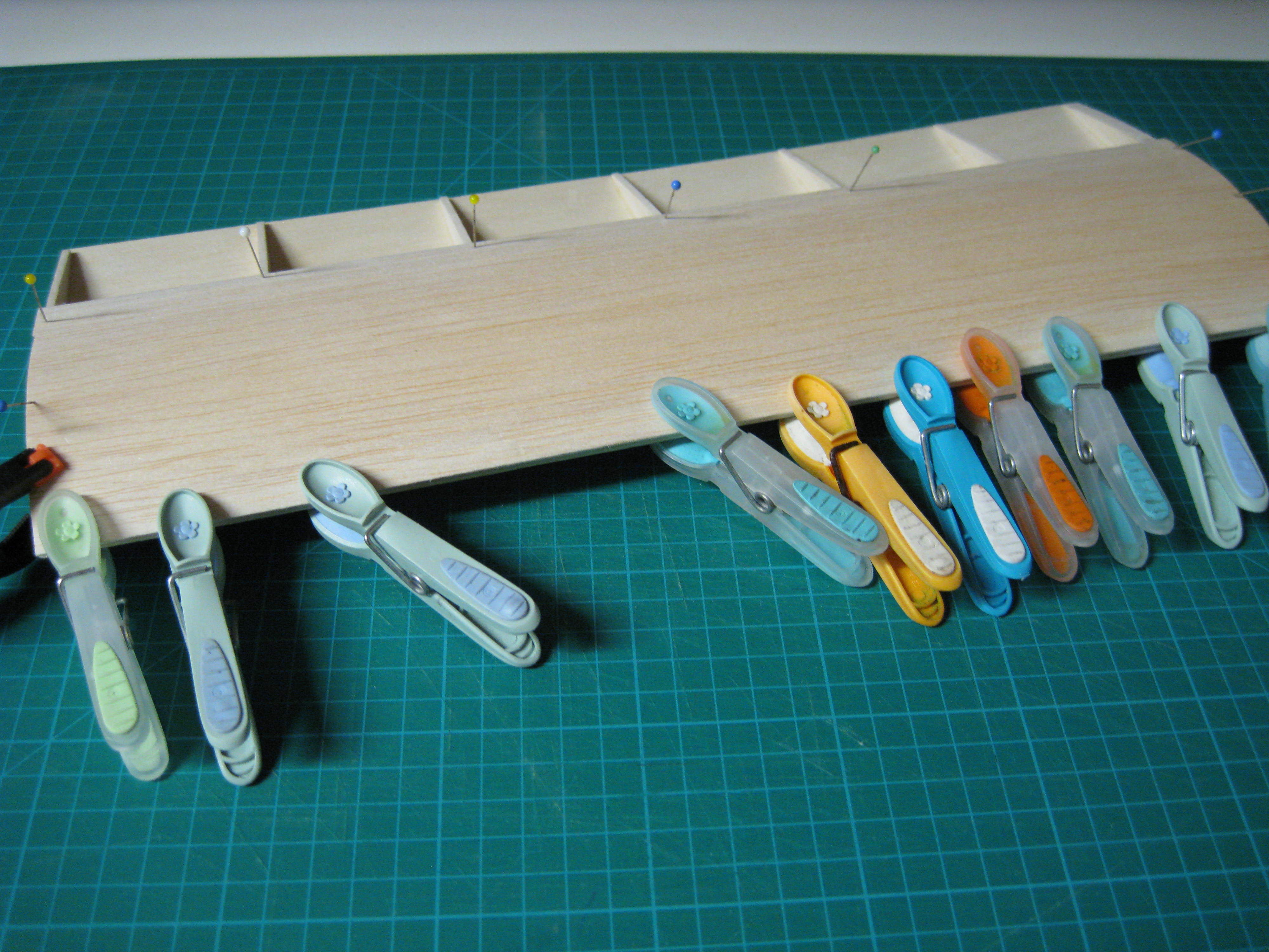
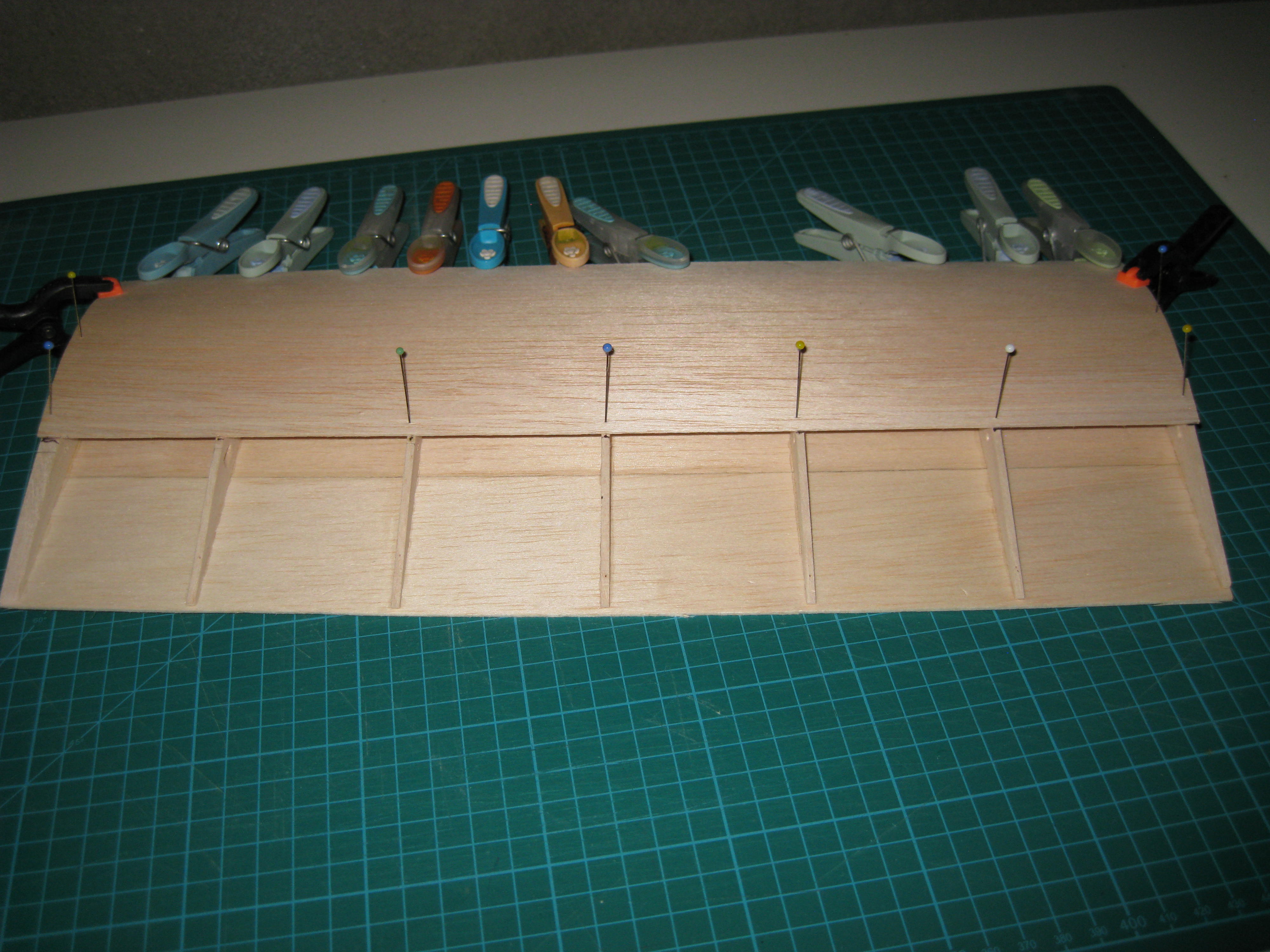 Add the rest of the top sheeting .
 Attach the wing tips and sand them to shape.
Support the wing tips to give the correct dihederal angle and join the two wing panels with two part epoxy adhesive.
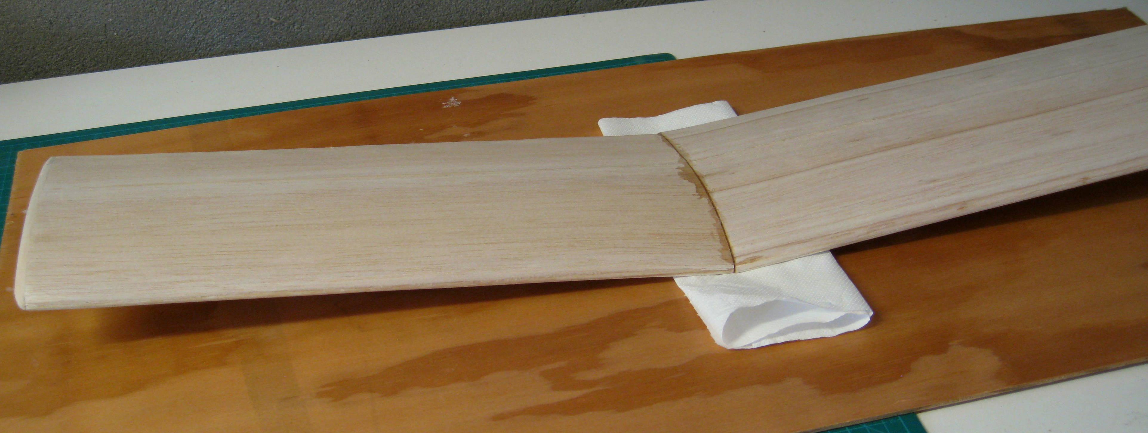
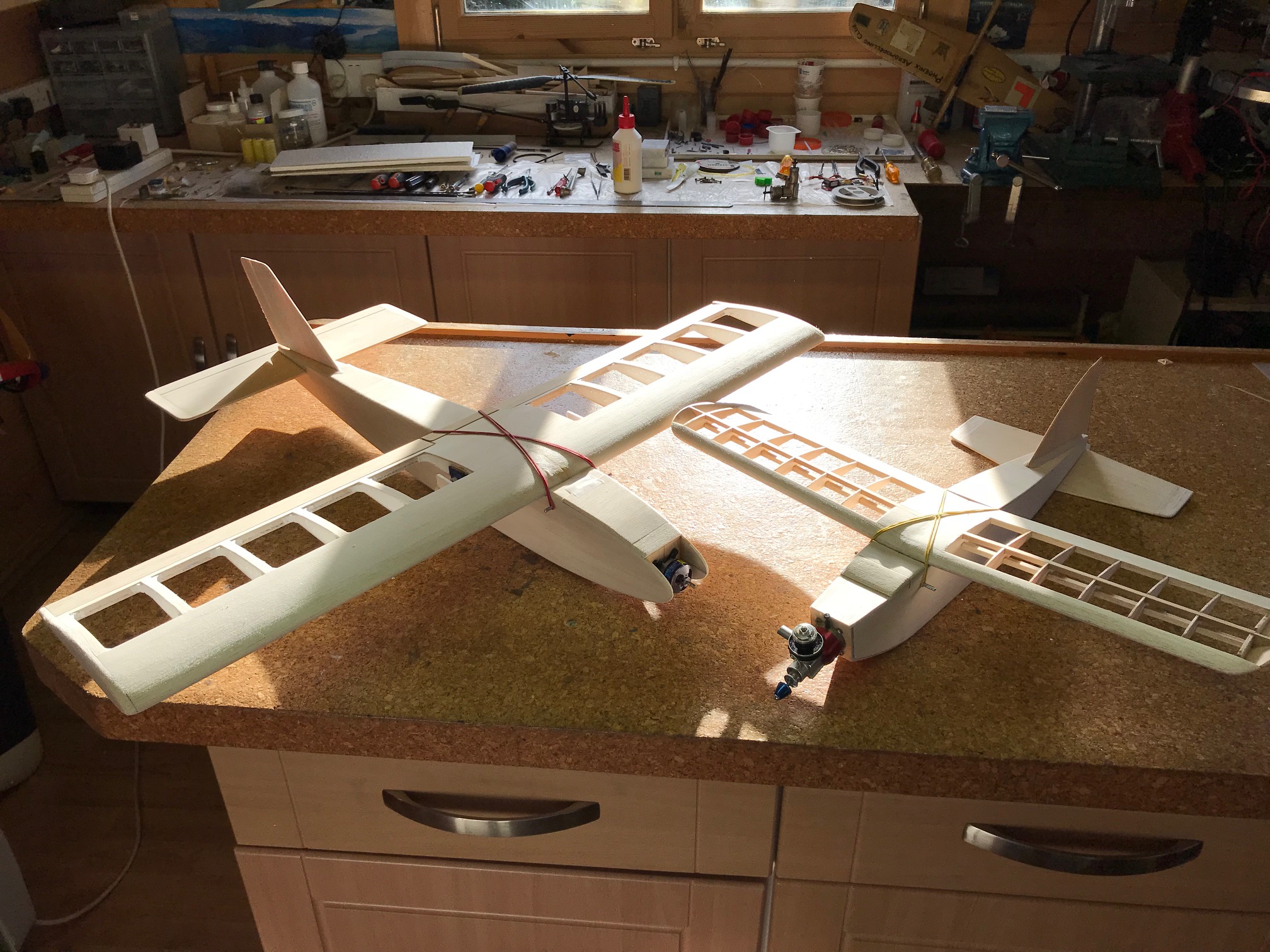
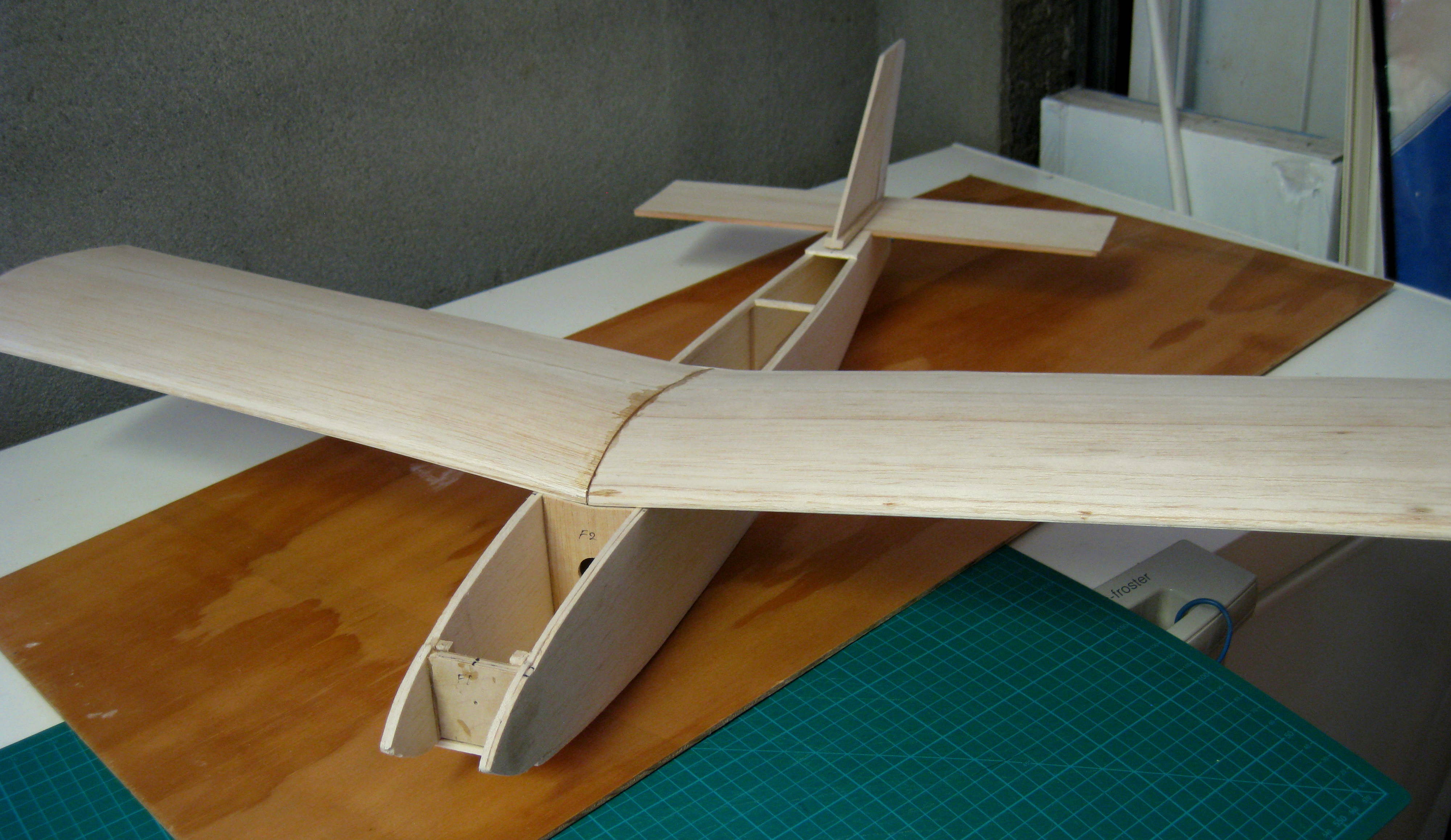
The bulk of the construction is now done and its even starting to look like an aeroplane!
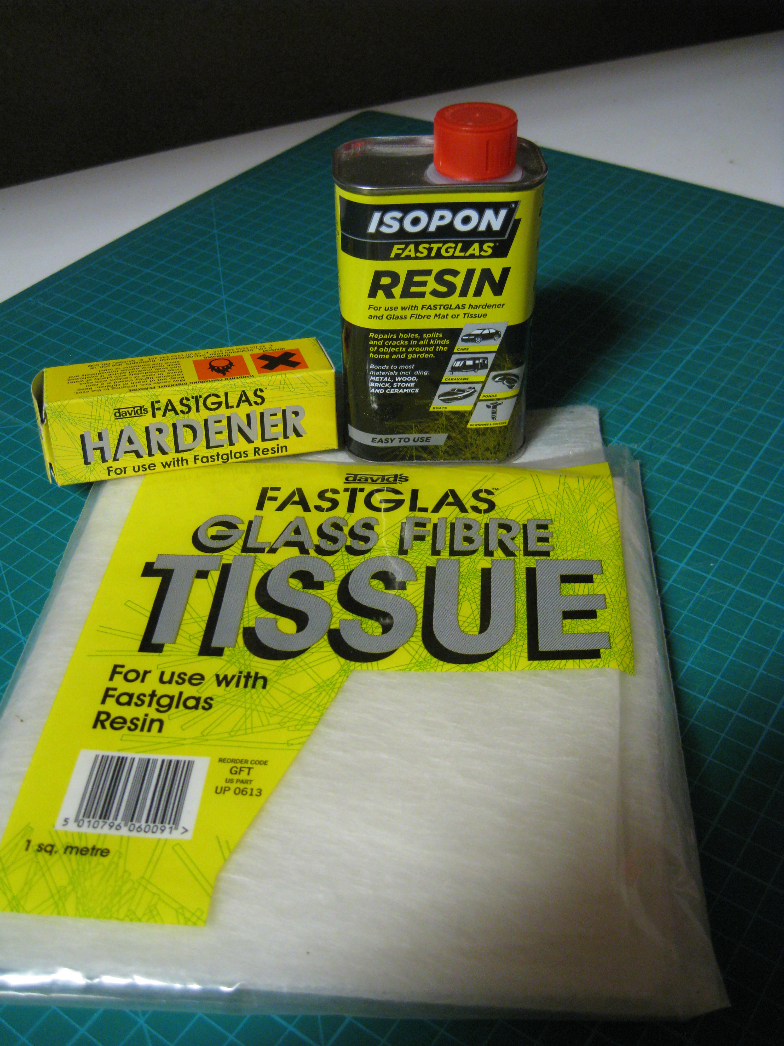
 Its not seen in the picture but I reinforce the wing join with some glass fibre tissue and resin.
Cover the wing. Cover the bottom panels first and then the top. Leave a small overlap from the top to the bottom.
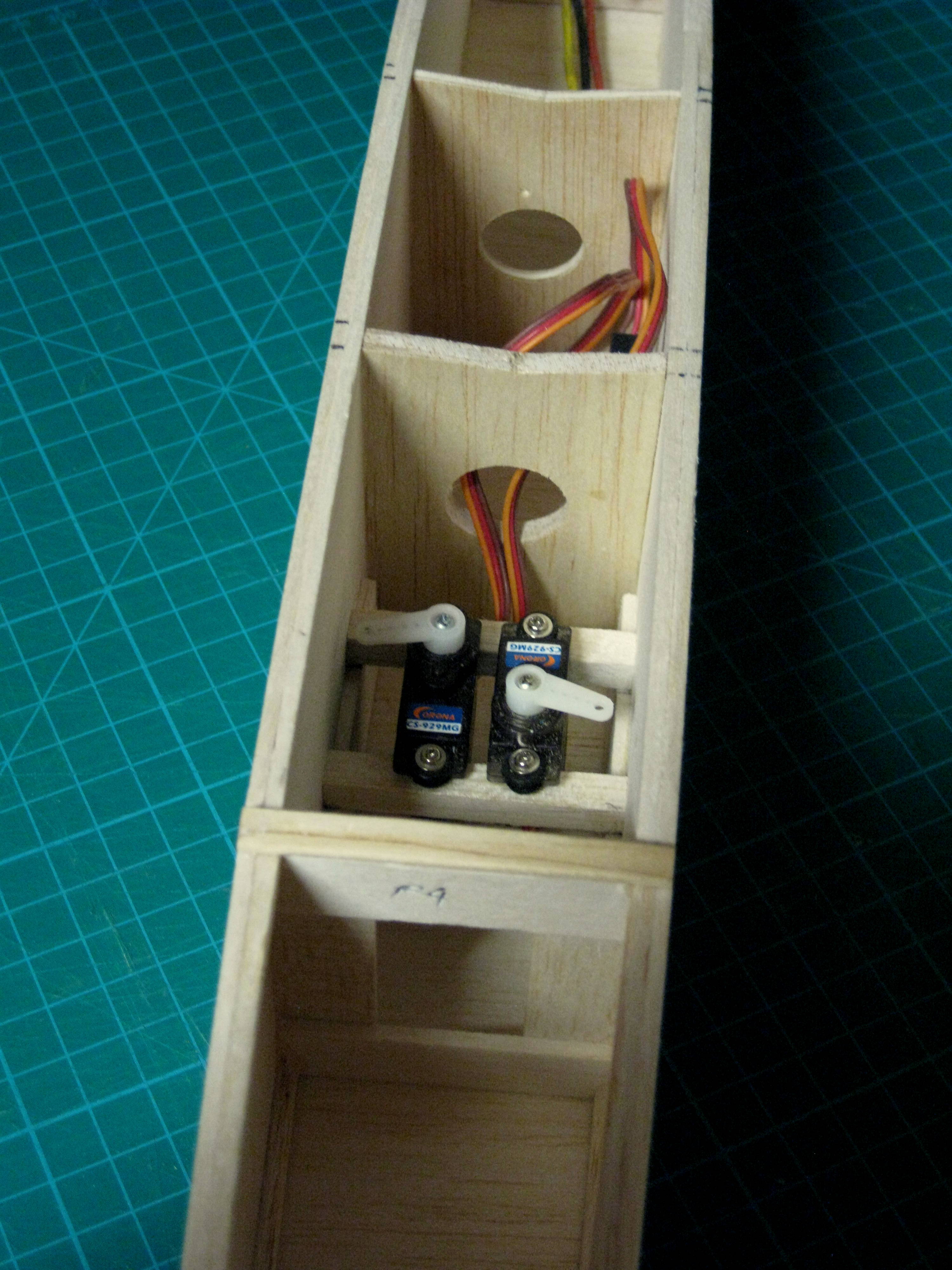
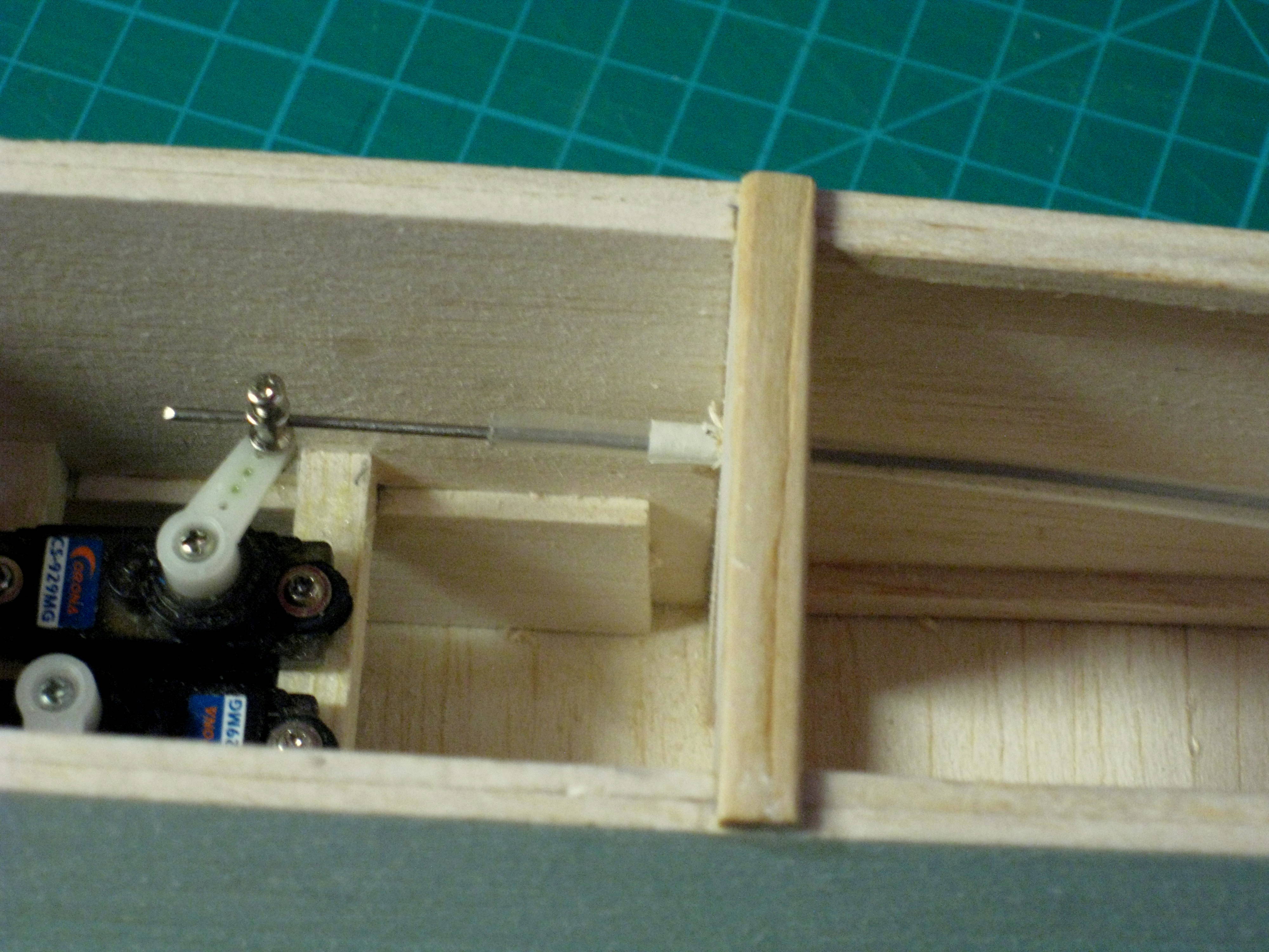
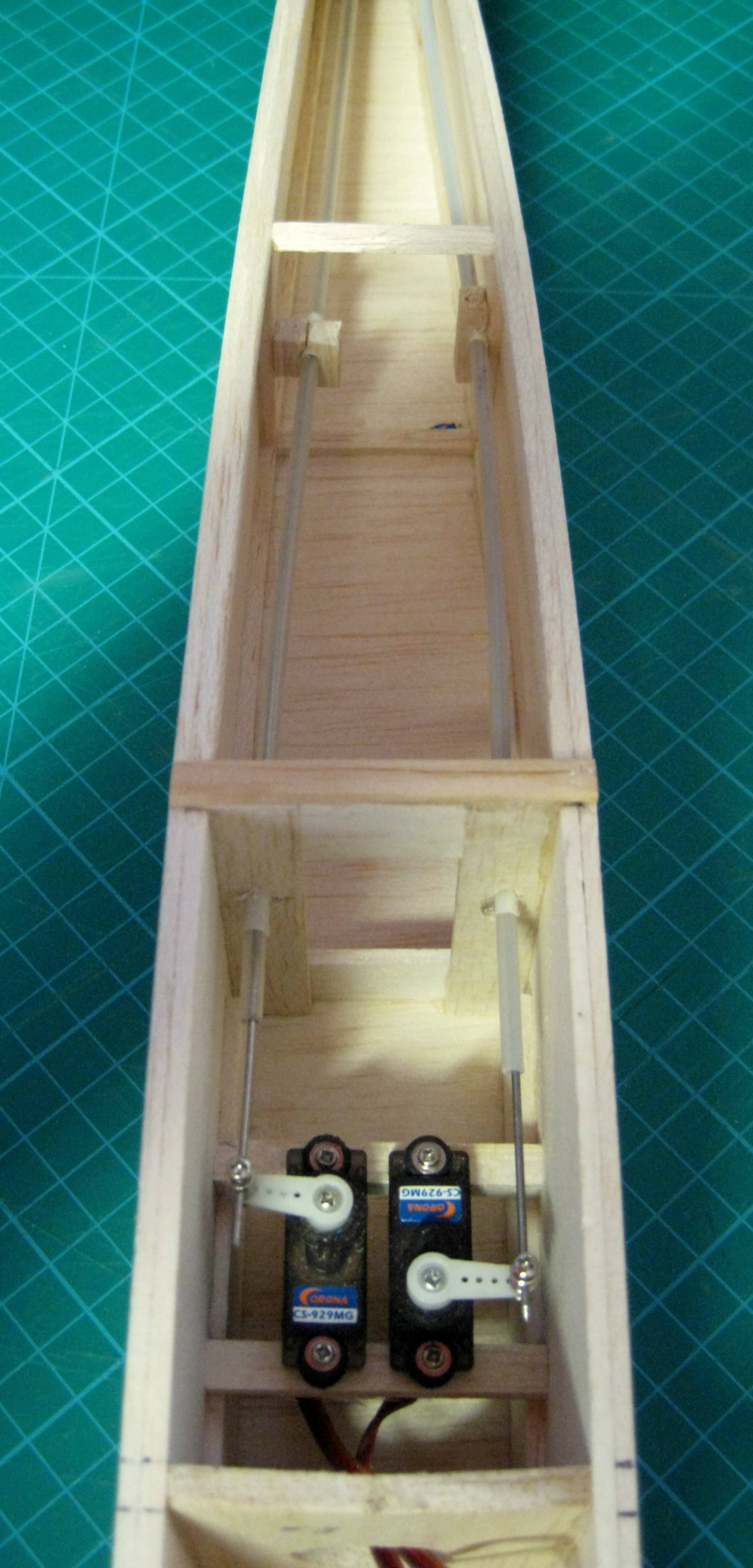
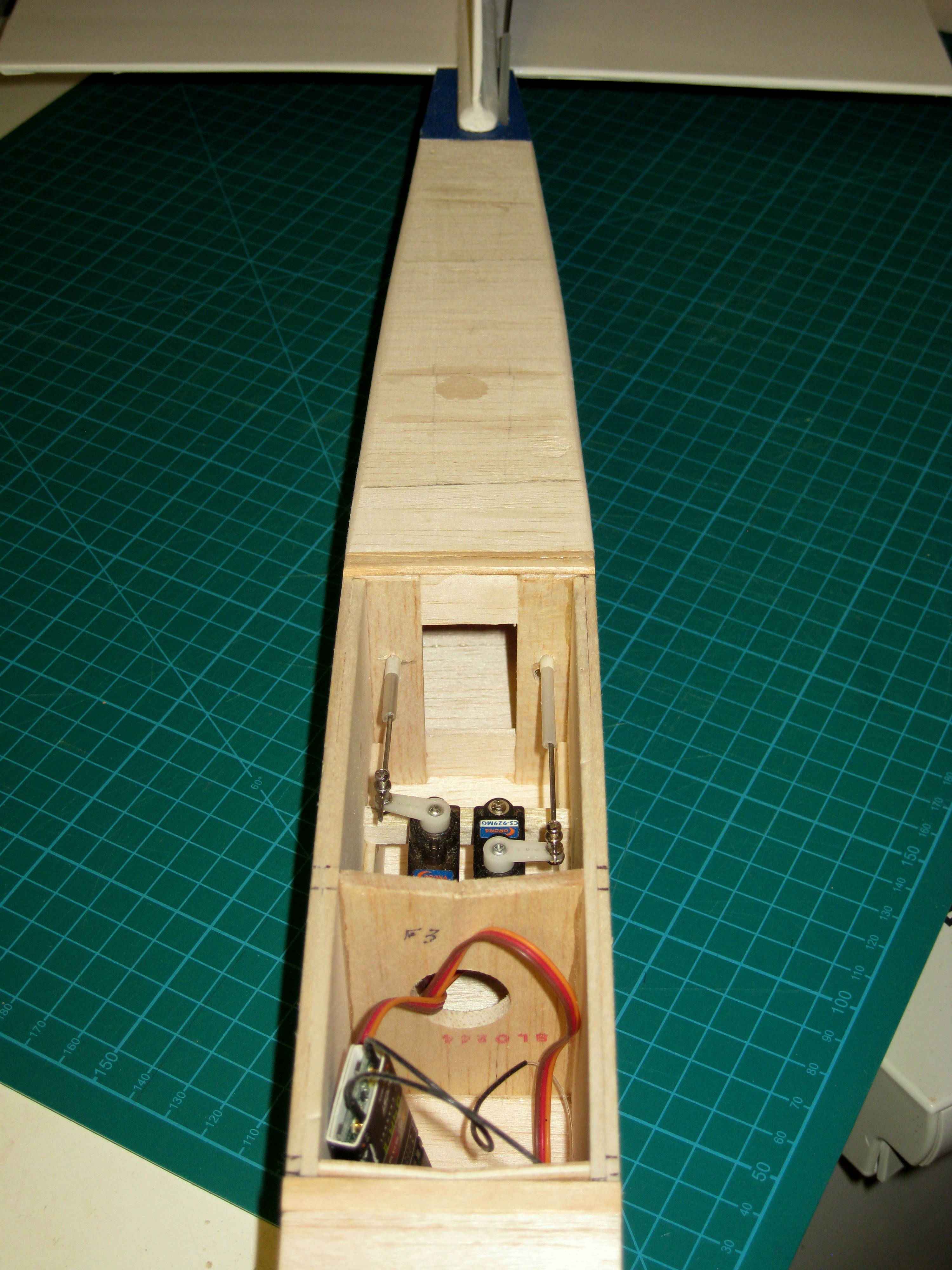
 Install supports for the servos between F3 and F4. These are just some scrap sheet glued to the fuz sides and some 1/4″ (4mm) balsa strip.
 Install the servos.
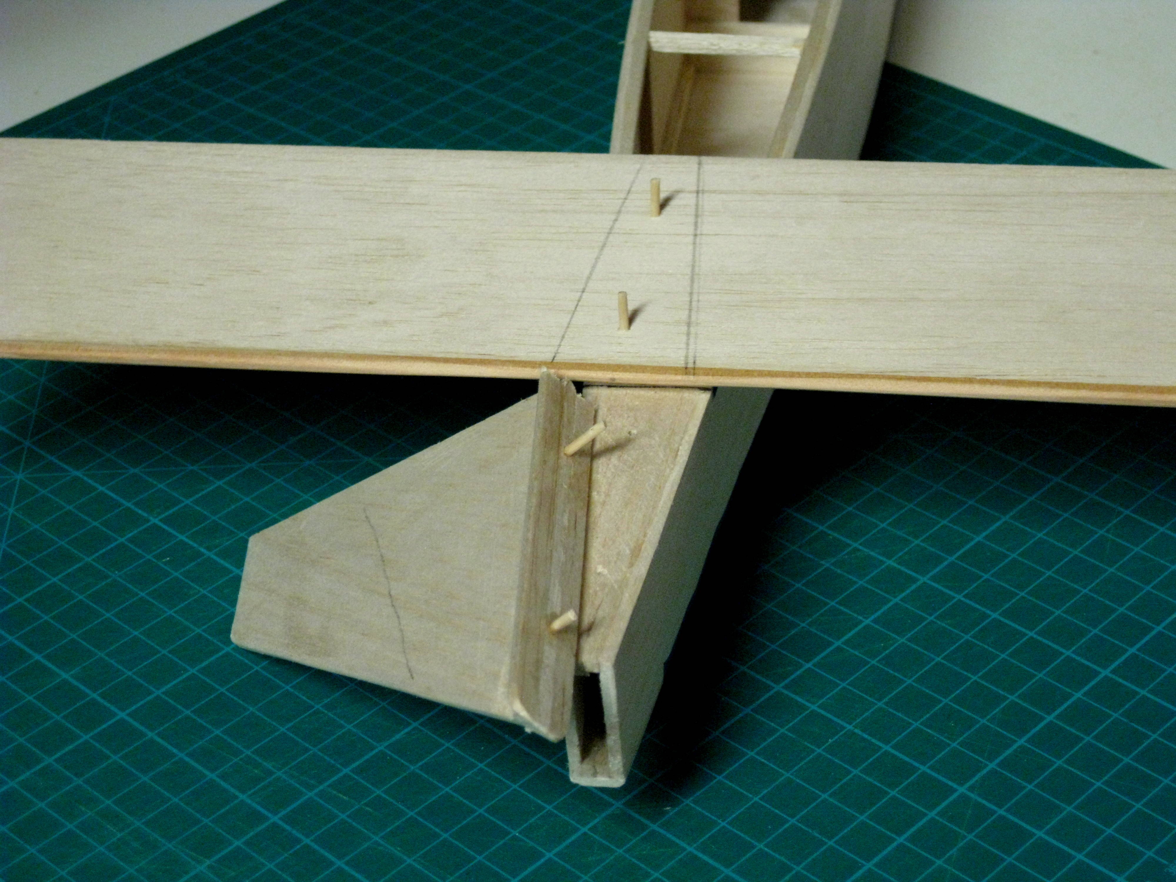
 Line up the Tailplane and Fin. Cocktail sticks are useful for keeping everything aligned and in the right ball park.
 Chamfer the trailiong edge of the tailplane to about 45deg. Line up the elevator and attach a strip of iron on film to keep the two surfaces together and act as a hinge.
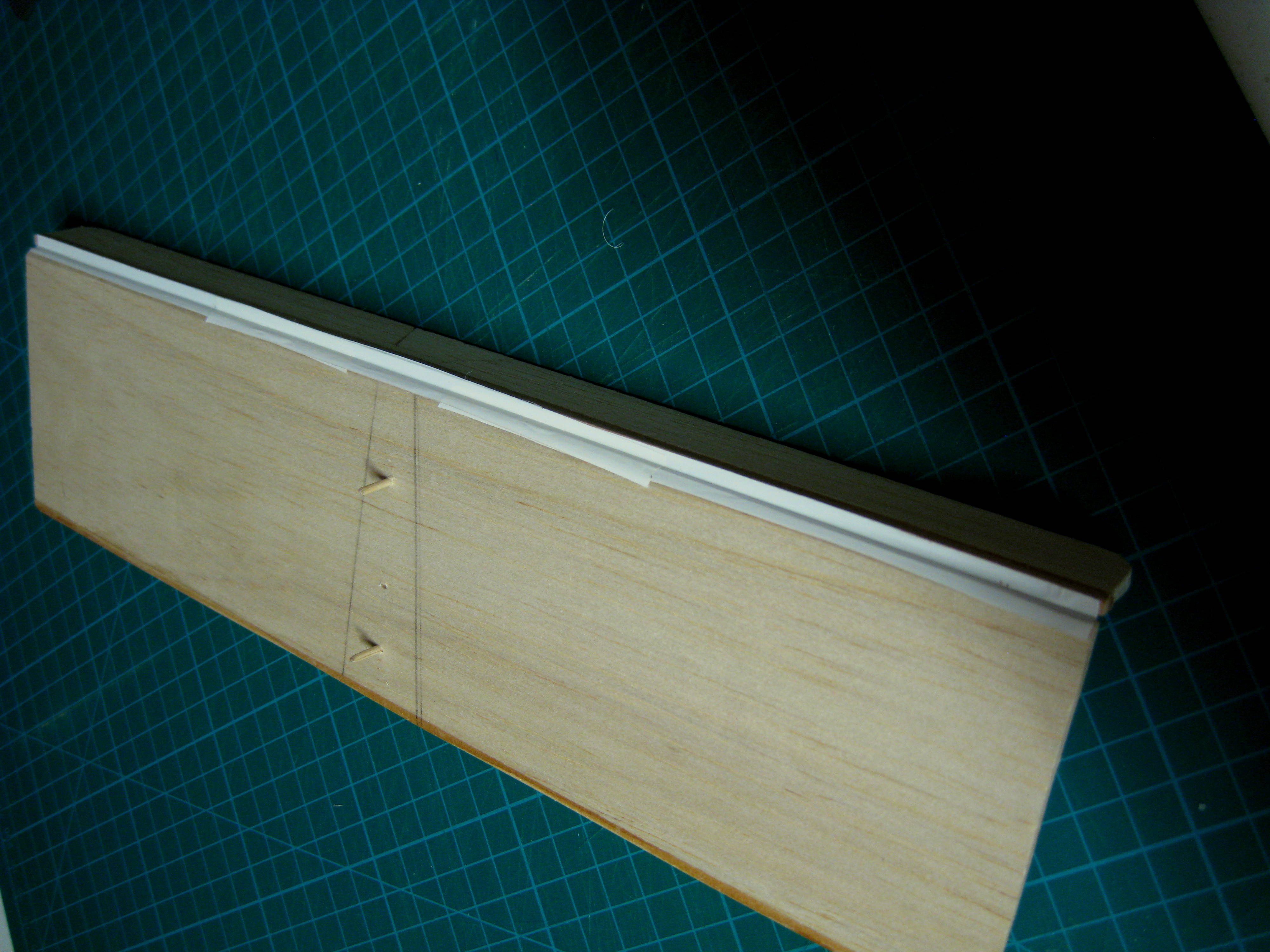 Cover the tailplane in the same order as the wing, Bottom first, then the top.
Cut film from the area that will attach to the fuz. Don’t glue film to film.
Glue the tailplane to the fuselage.
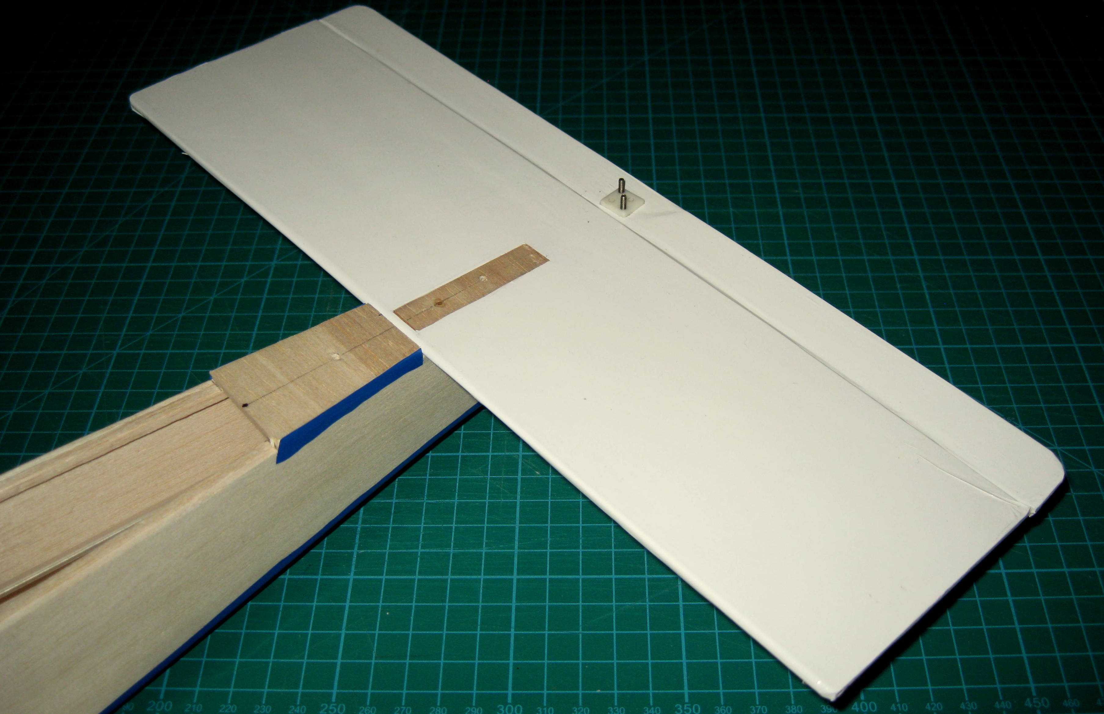 Install the elevator control horn and pushrod or snake. The pushrod can exit through the end of the fuselage A simple “Z” bend can be used to attach it at the elevator.
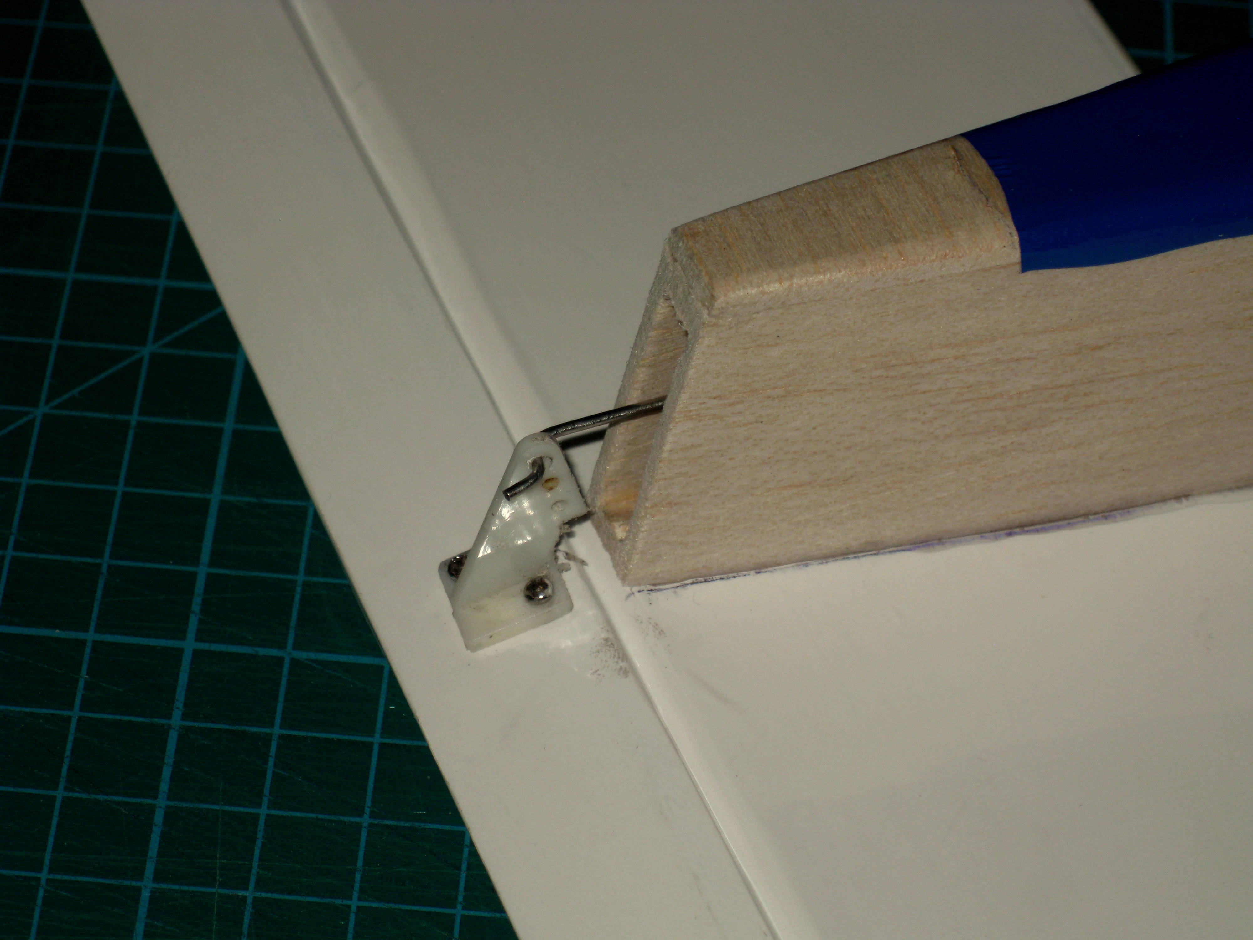 Adjustments can be made at the servo end.
 Hinge, cover and attach the fin in the same way as the tailplane. Exit the pushrod on the top of the fuz.
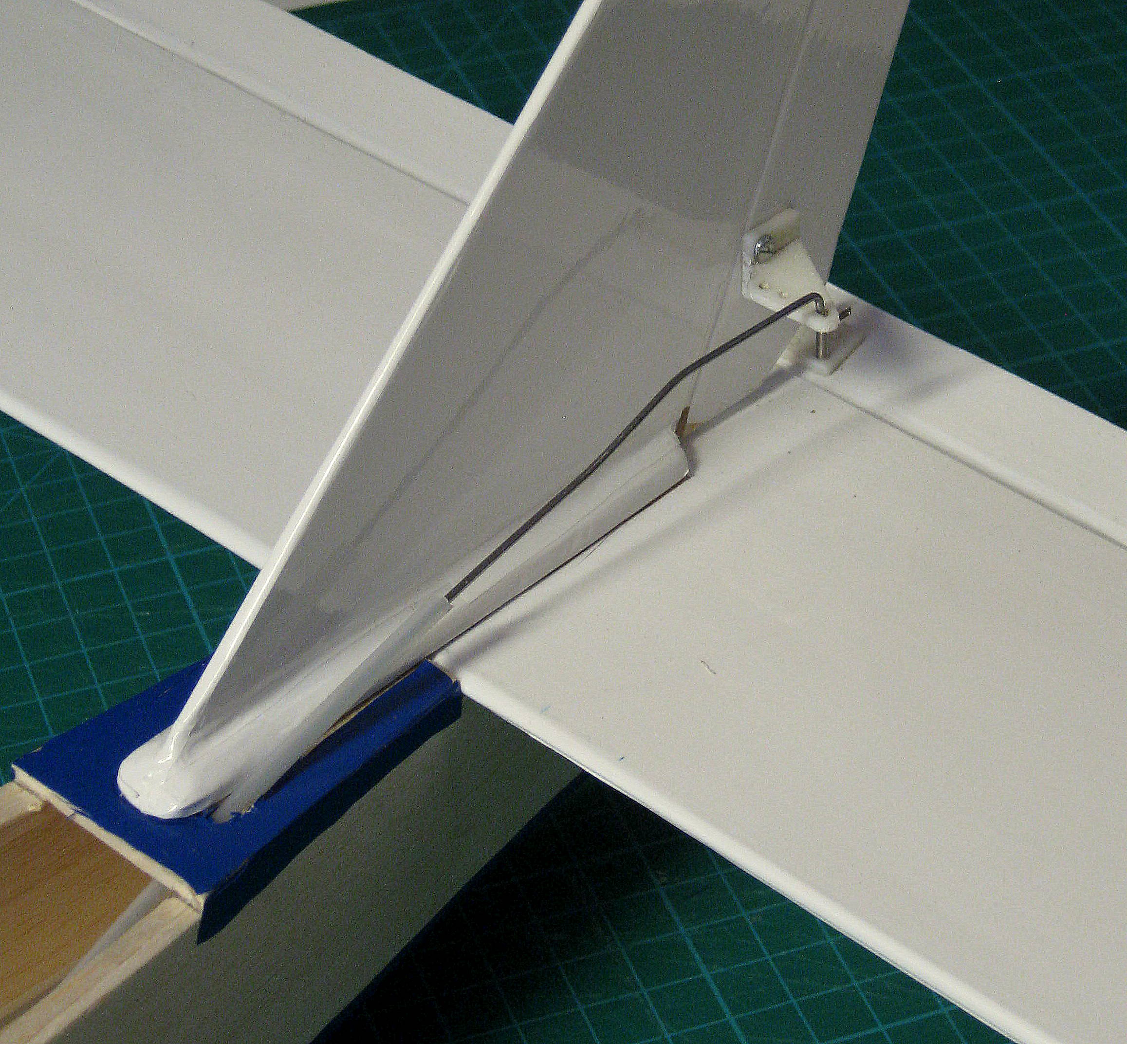 Both control surfaces are now secured and connected.
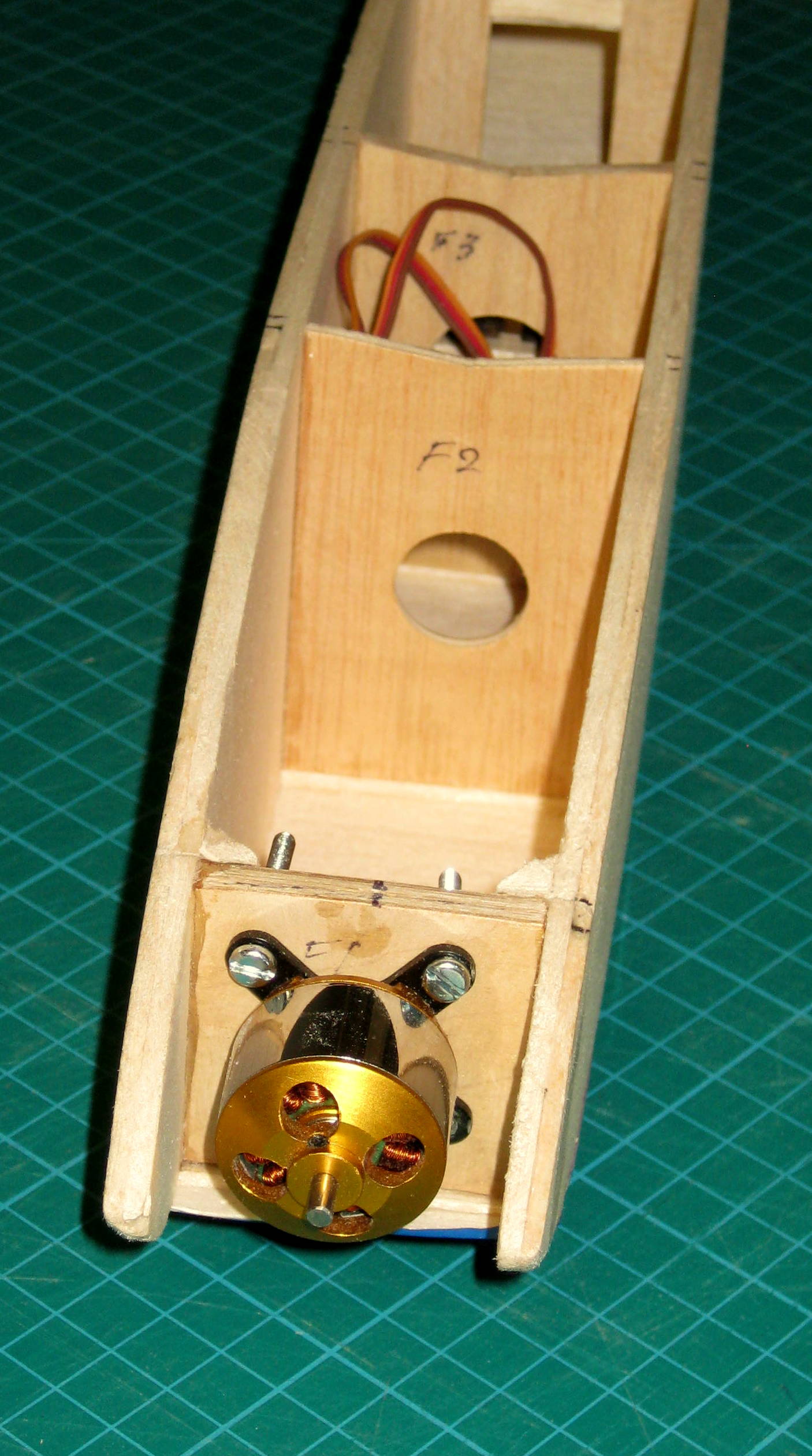
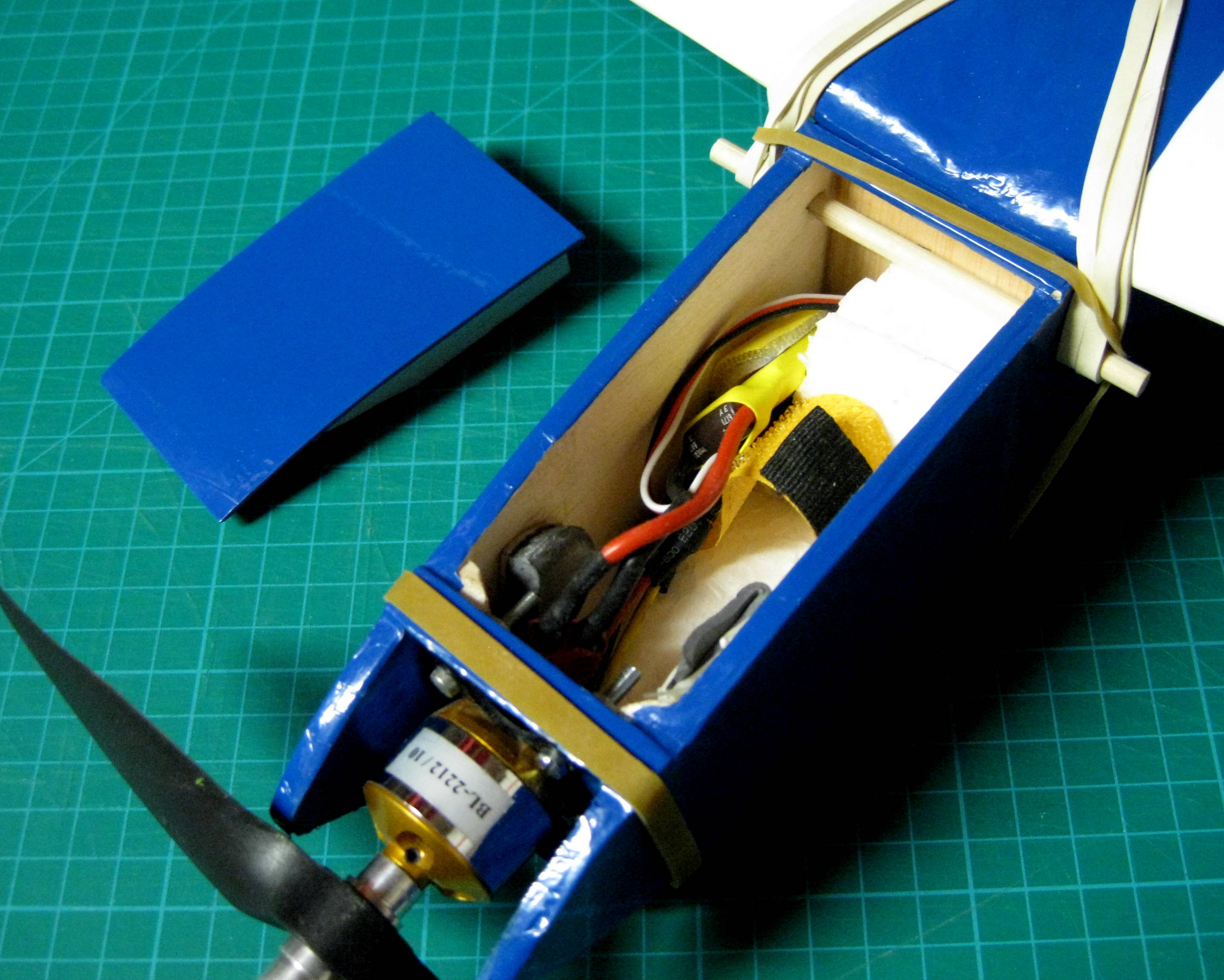
 Fit the motor to the firewall with screws and nuts (3mm).
Drill a hole at the bottom to let the wires through.
 Sheet the fuselage top, crossgrain, and round off the edges.
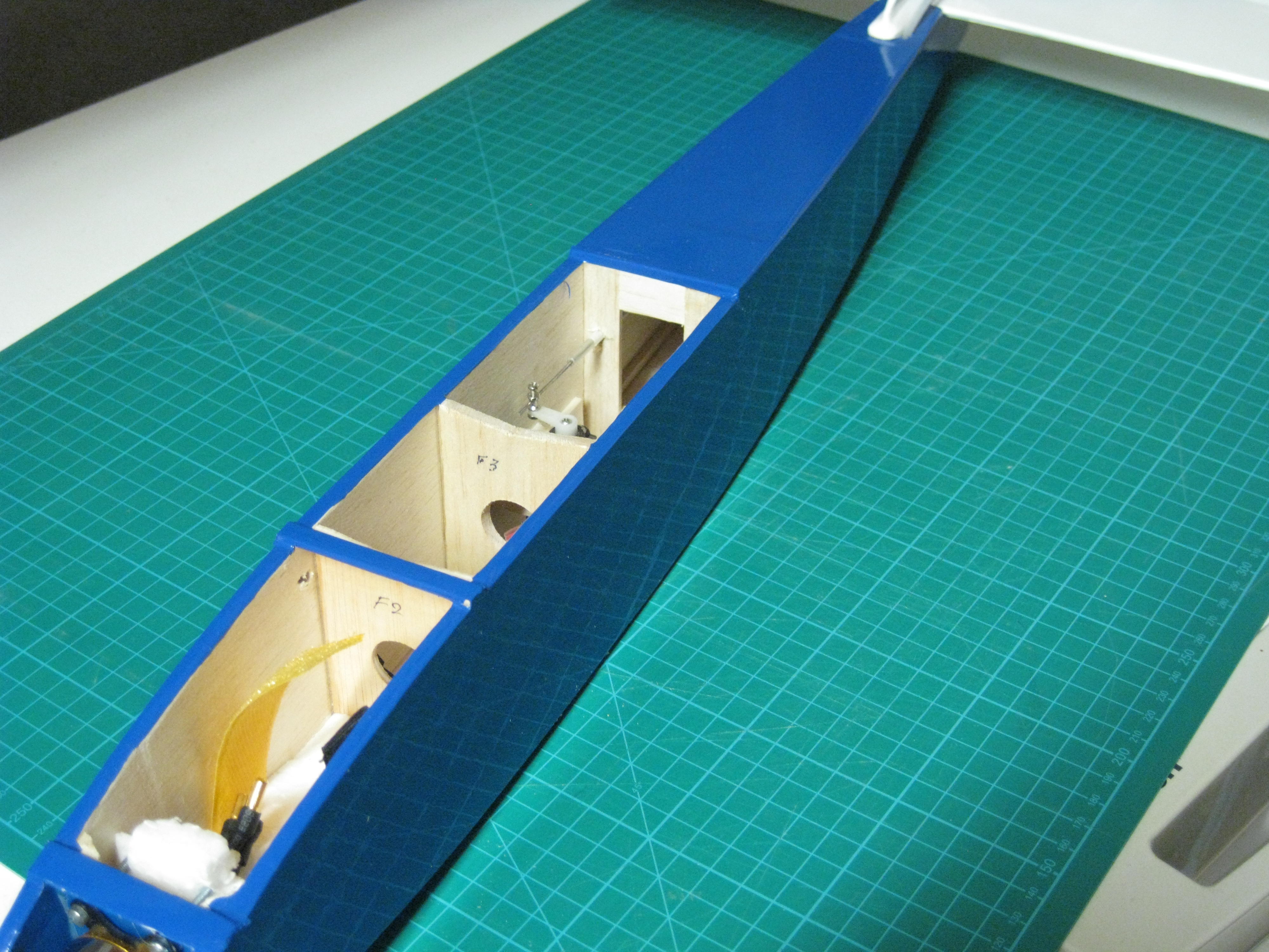
 Cover the fuselage, starting with the bottom, then the sides ald lastly the top.
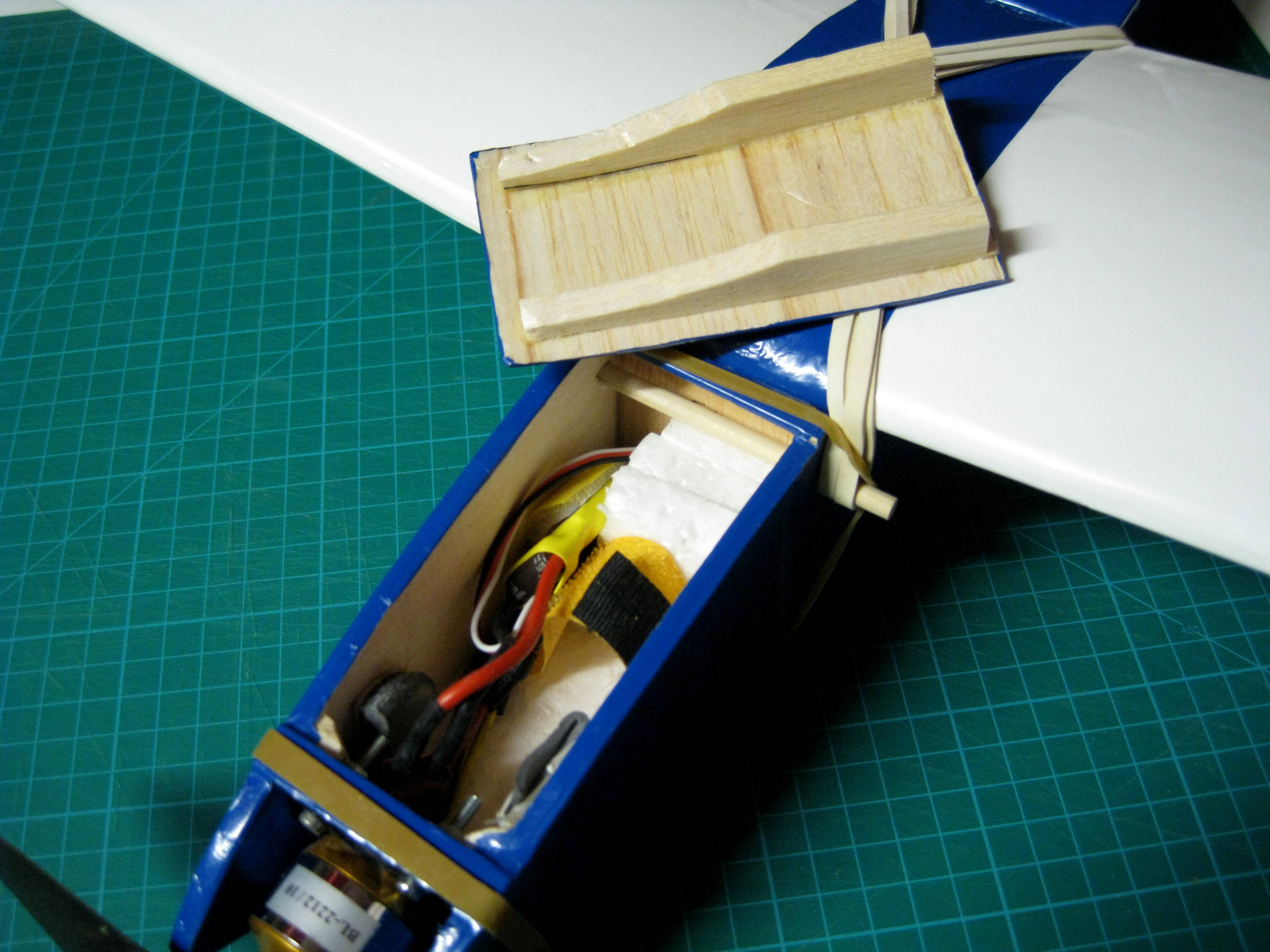
 Install the ESC, Battery, Receiver and Lost Model Alarm. (Recommended)
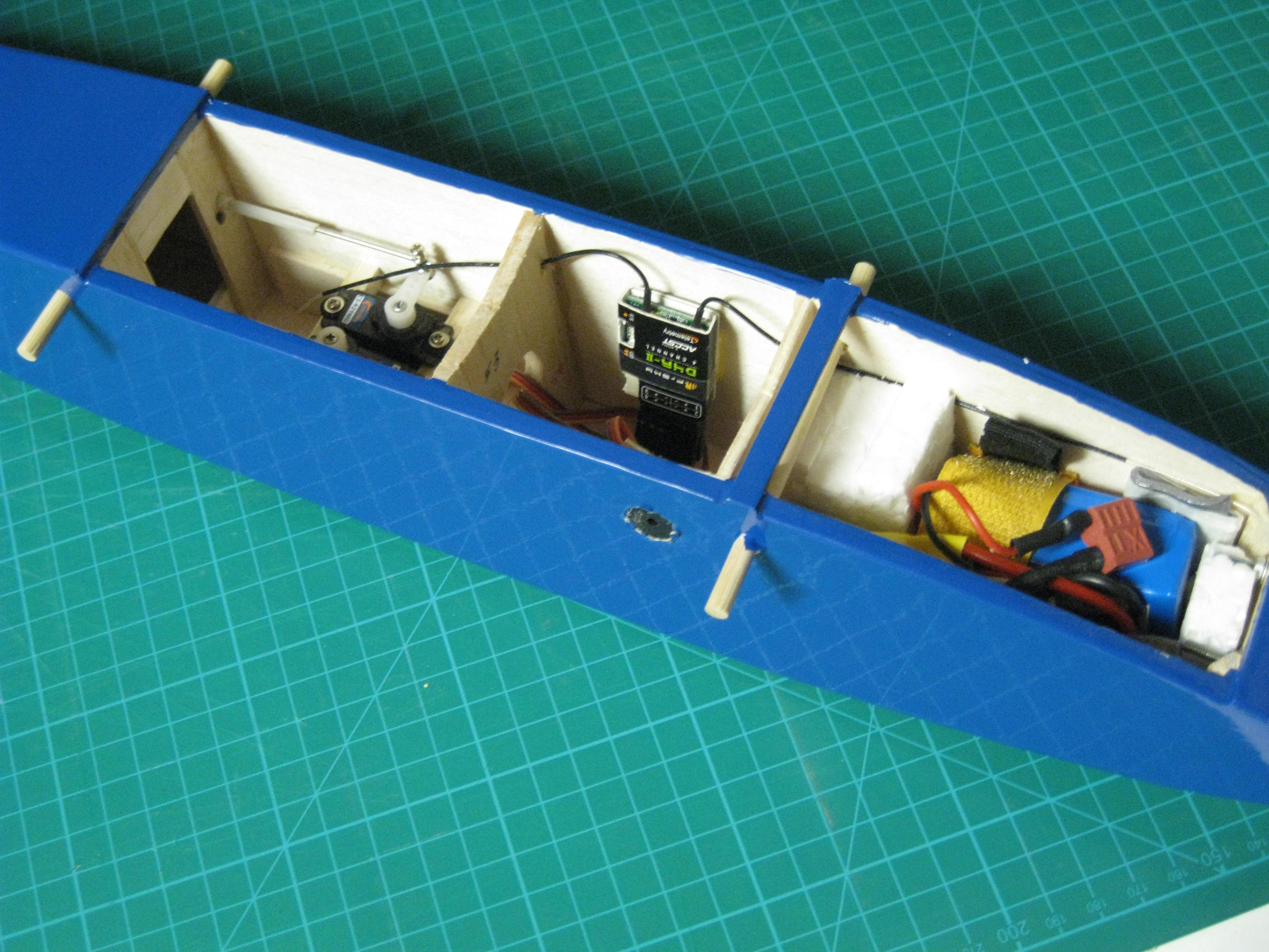 Fashion a battery compartment harch from scrap wood.
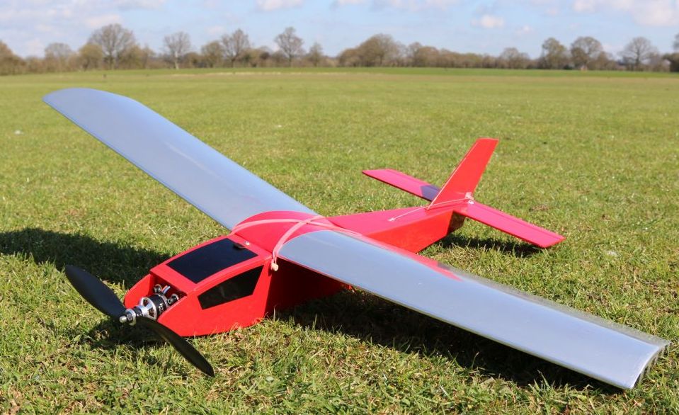
 Put it all together, balance the Sleeker 50mm from the wing l.e.at the root, charge the battery, do a range check, go flying………….
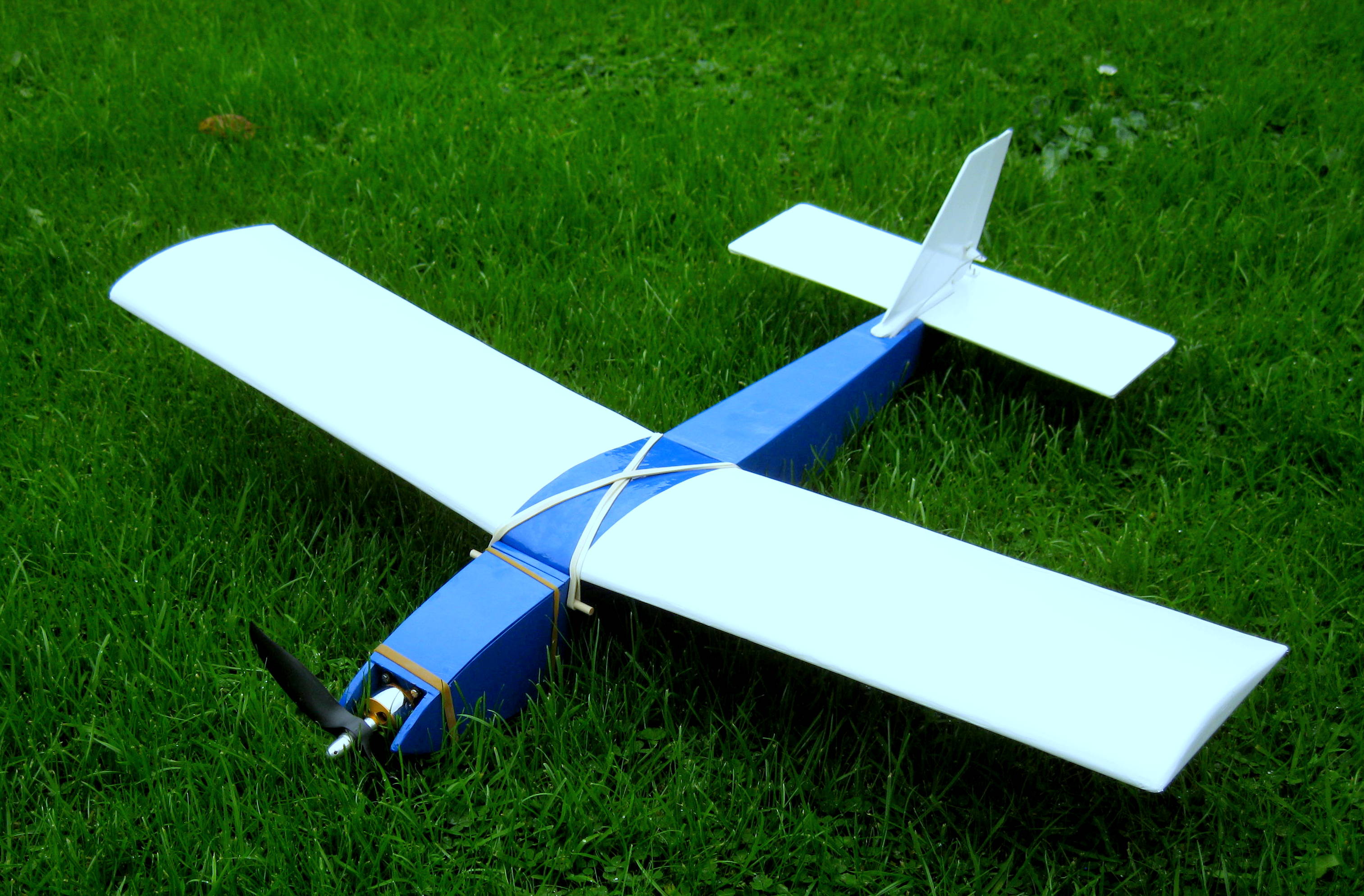 ……….. and have some fun!!
https://www.youtube.com/watch?v=r-LW8jN9ANs
https://www.youtube.com/watch?v=eXTeXFasUd4
Eanna’s Sleeker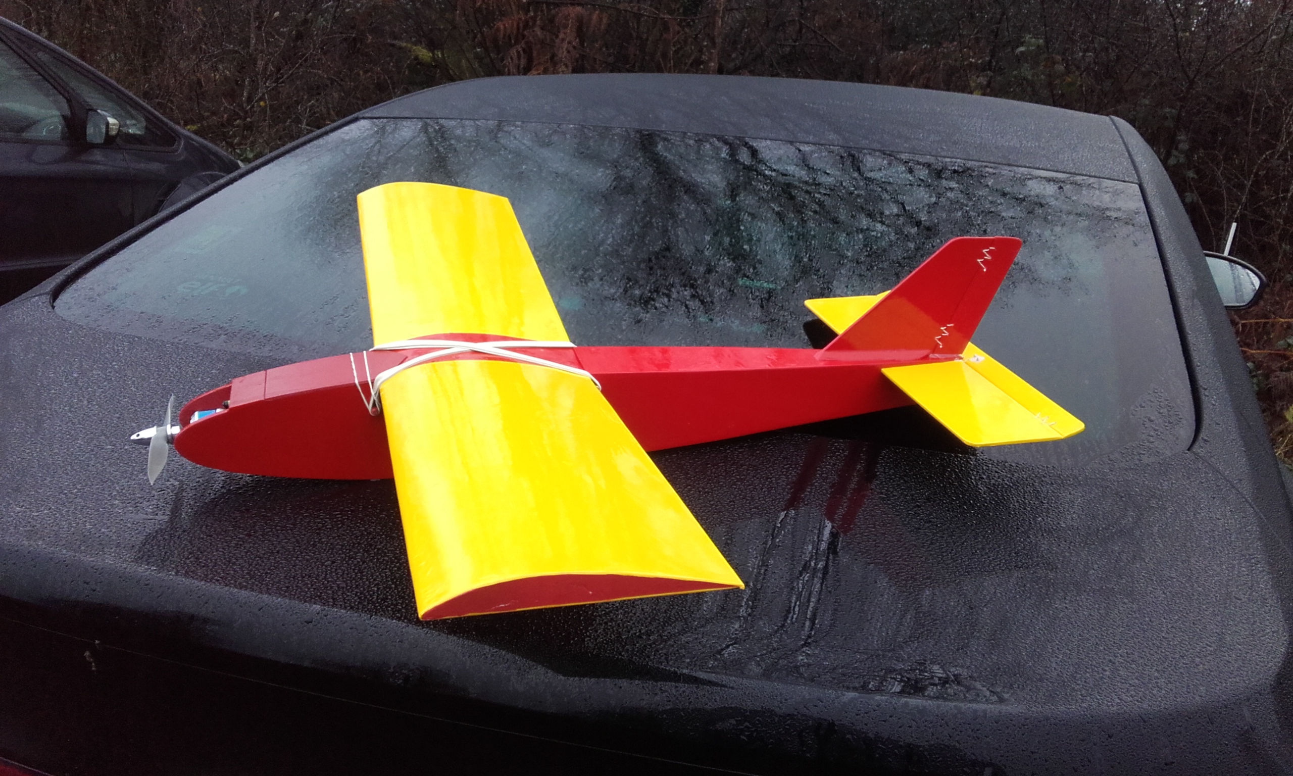 Declan’s Sleeker.
 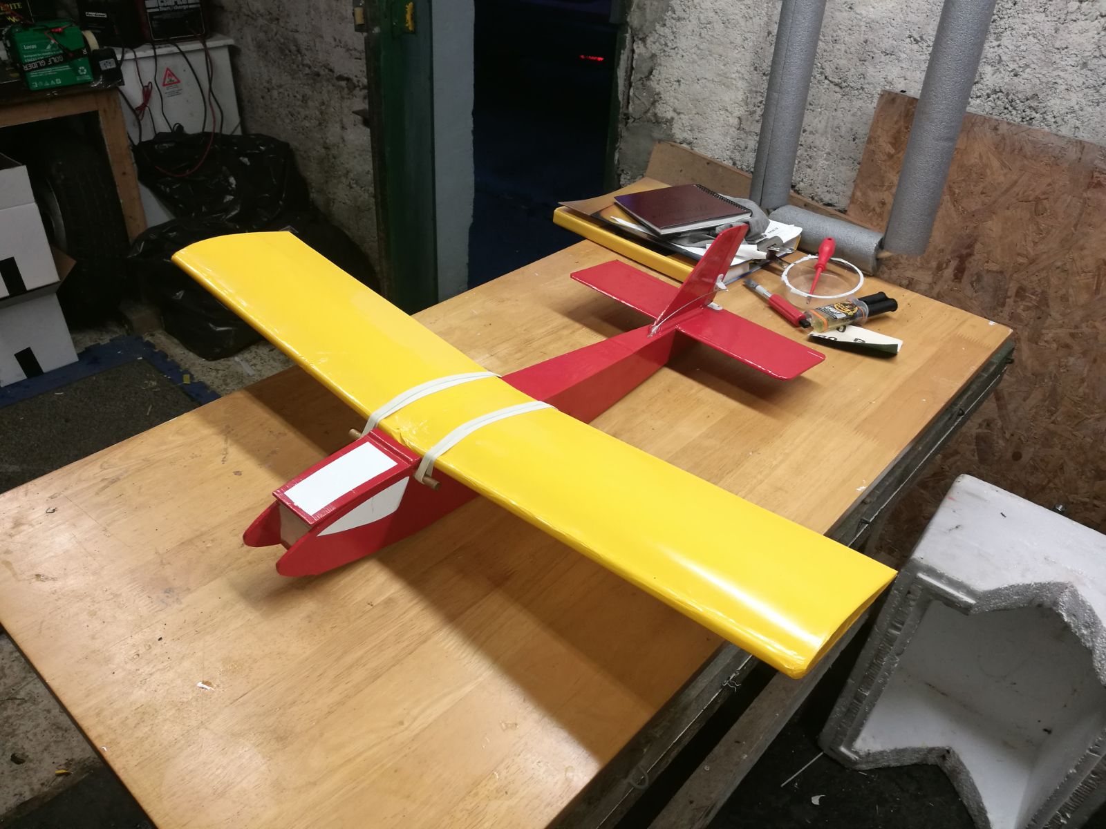 Stu’s Sleeker and Sharkface.